Mounting structure for power module, and motor controller including the same

a technology of motor controller and mounting structure, which is applied in the direction of electrical apparatus construction details, electrical apparatus casings/cabinets/drawers, instruments, etc., can solve the problems of damage to the power module b>3/b>, additional labor and time, and damaged printed circuit boards b>4/b> and the power module b>a /b>, etc., to achieve easy disassembly and separation, and easy separation

Inactive Publication Date: 2010-04-15
YASKAWA DENKI KK
View PDF9 Cites 12 Cited by
  • Summary
  • Abstract
  • Description
  • Claims
  • Application Information

AI Technical Summary

Benefits of technology

[0018]With the mounting structure for a power module according to claims 1 and 2, in order to disassemble the structure from a state in which the power module has been connected to the printed circuit board by soldering and the power module, the printed circuit board, and the heat sink have been assembled, the power module and the heat sink can be easily separated from each other by loosening the power module fixing screws with a tool from the heat radiation fin side of the heat sink, without forming screw removal holes in positions in the printed circuit board in which the power module fixing screws are disposed as in the existing technique.
[0019]Moreover, the power module and the heat sink can be easily separated from each other without additional labor and time, without requiring an extra disassembly space in a product, and without damaging parts during the disassembly.
[0020]With the mounting structure for a power module according to in claims 3 and 4, by forming the screwdriver slot or the wrench socket on the end portion of the power module fixing screw on the side of the fixing screw opposite to the screw head, the printed circuit board and the power module can be easily separated from the heat sink with a tool such as a screwdriver or a wrench after having been assembled.
[0021]Because the power module and the heat sink are separated from each other after having been assembled, the parts are not damaged and can be reassembled.
[0022]With the mounting structure for a power module according to claim 5, by forming the hole for inserting the power module fixing screw in the recessed mounting eye of the power module in the position of the power module facing the screw holes of the heat sink, the screw head of the power module fixing screw is prevented from contacting a protrusion or the like on the printed circuit board.
[0023]With the motor controller according to claim 6, by applying the mounting structure for a power module according to any one of claims 1 to 5 to the motor controller, the advantage according to claims 1 to 5 can be easily gained, and, for example, assembling and disassembling can be easily performed when a power module is installed in a device such as an inverter.

Problems solved by technology

Therefore, the existing mounting structure for a power module has a problem in that additional labor and time are necessary because the power module 3 and the heat sink 5b can be separated from each other only by melting and removing the solder with a desoldering tool.
Therefore, the existing structure has another problem in that the printed circuit board 4a and the power module 3 are damaged by the excessive heat stress and cannot be reused.
However, when the screw removal holes 7b are formed, a space for disposing pattern wiring and parts on the printed circuit board is reduced, which causes a problem in that miniaturization is hindered.

Method used


Image

  • Mounting structure for power module, and motor controller including the same
  • Mounting structure for power module, and motor controller including the same
  • Mounting structure for power module, and motor controller including the same

Examples


first embodiment

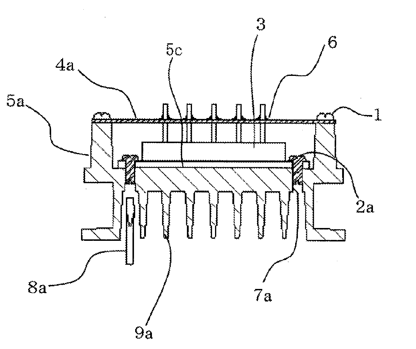
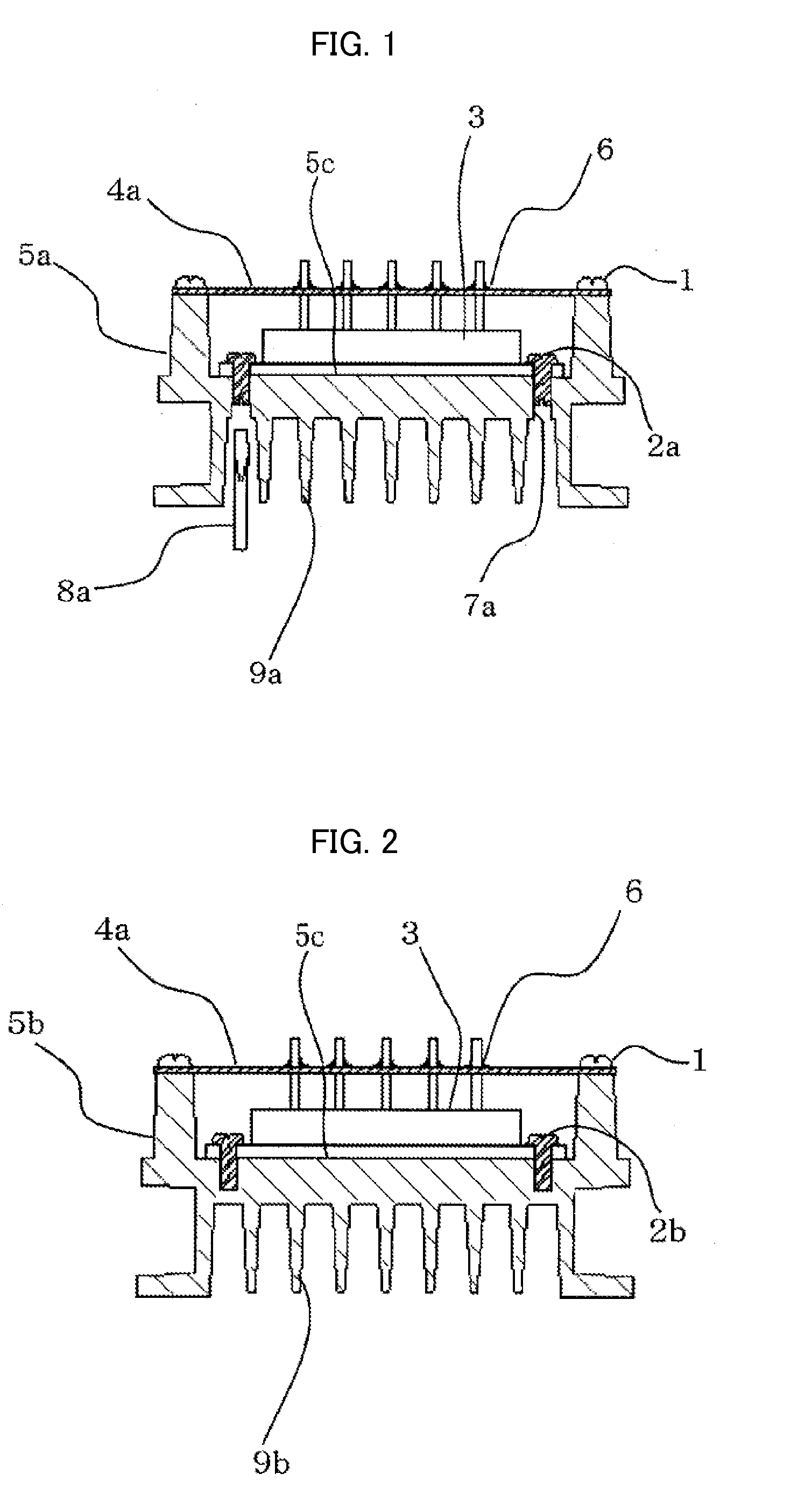
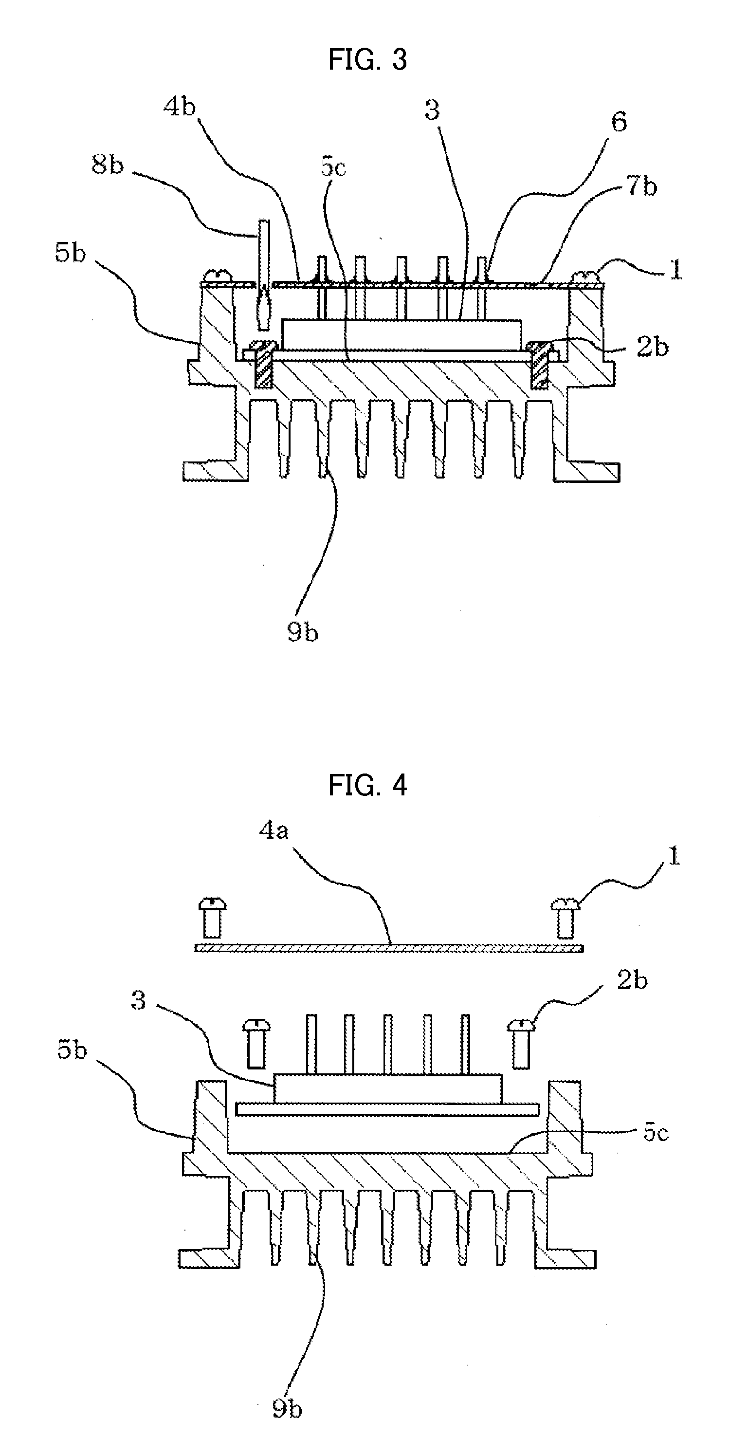
[0047]FIG. 1 is a sectional side view of a mounting structure for a power module showing an embodiment of the present invention; FIG. 5 is a general perspective view of the power module; FIG. 6 is an external view showing a power module fixing screw of the embodiment, in which (a) is a front view and (b) is a bottom view (screwdriver slot); and FIG. 7 is an external view showing a power module fixing screw of the embodiment, in which (a) is a front view and (b) is a bottom view (wrench socket).

[0048]FIGS. 1 and 5 show printed circuit board fixing screws 1, power module fixing screws 2a, mounting eyes 3a, holes 3b, a printed circuit board 4a, a heat sink 5a, a power module mounting surface 5c, soldered portions 6, screw holes 7a, a tool 8a, and heat radiation fins 9a.

[0049]The present invention is different from the existing technique in that, in the heat sink 5a, the screw holes 7a having female screw threads (taps), into which the power module fixing screws 2a for fixing the power...


PUM


Abstract

A mounting structure for a power module, in which a power module and a heat sink can be easily separated without additional labor and time and without requiring an extra disassembly space in a product and in which parts are not damaged during the disassembly. In the heat sink (5a), screw holes (7a) having female screw threads into which power module fixing screws (2a) are screwed are formed so as to penetrate a power module mounting surface (5c) of the heat sink (5a) and heat radiation fins (9a). The power module fixing screw (2a) is constructed such that, to mount the power module (3) on the heat sink (5a), the screw head of the power module fixing screw (2a) is tightened from the printed circuit board (4a) side with a tool (8a) and that, to remove the power module (3) from the heat sink (5a), the power module fixing screw (2a) is loosened with the tool (8a) from the heat radiation fin (9a) side on the opposite side of the screw head.

Description

TECHNICAL FIELD [0001]The present invention relates to a power module used in the field of power electronics, mainly a motor controller such as an inverter or a servo amplifier operated with high-voltage electric power, the power module including a power semiconductor device that is an exothermic component. In particular, the present invention relates to a mounting structure for fixing the power module to a heat sink including a plurality of heat radiation fins for cooling the power module, and to a motor controller including the mounting structure.BACKGROUND ART[0002]Patent Document 1, for example, has proposed a mounting structure for a power module used in the field of power electronics, mainly a motor controller such as an inverter or a servo amplifier operated with high-voltage electric power, the power module including a power semiconductor device that is an exothermic component.[0003]FIG. 2 is a sectional side view showing the existing mounting structure for a power module, F...

Claims


Application Information

Patent Timeline
Patent Type & Authority Applications(United States)
IPC IPC(8): H05K7/20
CPCH01L23/3675H01L23/4006H01L25/162H01L2023/405H01L2023/4087H01L2924/0002H05K7/209H01L2924/00
Inventor YAMANAKA, YASUNORI
Owner YASKAWA DENKI KK
Why Eureka
Try Eureka