Plate-laminated type fuel cell

a fuel cell and plate-laminated technology, applied in the direction of fuel cells, solid electrolyte fuel cells, cell components, etc., can solve the problems of 4 structural problems, so as to prevent damage to the power generation cell, reduce local deformation of the arm section under load at high temperature, and the length of the arm section can be sufficien

Inactive Publication Date: 2010-04-15
AKBAY TANER +3
View PDF6 Cites 9 Cited by
  • Summary
  • Abstract
  • Description
  • Claims
  • Application Information

AI Technical Summary

Benefits of technology

[0017]According to the present invention, since the elastic deformation of the arm section of the separator is kept in the range of elastic deformation under high temperature atmosphere at the time of power generation, undesirable stress which is likely to occur in the power generation cells due to plastic deformation of the arm sections in the process of falling temperature can be minimized and, accordingly damage to the power generation cell can be prevented.
[0018]In particular, since the proximal portion of the arm section is located at diagonal position of the distal end of the arm section, it is possible to ensure sufficient length of the arm section. Thus, local deformation of the arm section under load at high temperature can be reduced, whereby the deformation of the arm section can be kept in the range of elastic deformation.
[0019]In addition, since the proximal portion of the arm section is located at diagonal position of the distal end of the arm section, distance between the interconnect section and the proximal portion of the arm section can be increased as much as possible. Therefore, the effect of the deformation force of the arm sections on the interconnect section can be minimized, and flatness of the interconnect section can be maintained. As a result, uneven load applied to the power generation cell can be prevented, and damage to the power generation cell can be prevented.
[0020]Further, since the corners of the arm sections are rounded to eliminate structural discontinuity, concentration of stress at the corners of the arm sections can be reduced, and local plastic deformation of the arm sections can be suppressed. Accordingly, the deformation of the arm section can be kept in the range of elastic deformation, and damage to the power generation cell can be prevented.

Problems solved by technology

However, especially in case of the plate-laminated type fuel cell having an internal manifolds, laminated elements in the power generating section located at the center of the stack are different from those in the manifold section located at the peripheral of the stack.
As a result, clamping force in each section is deficient due to difference in height between the sections, resulting in problems that adhesiveness between the elements is deteriorated, and the power generation cells are damaged by excess clamping force applied on the power generating section.
However, the separator shown in FIG. 4 has structural problems as described below.
When plastic deformation occurs in the arm sections 8b at the time of power generation as described above, undesirably large force is applied to the power generation cells 5 through the arm sections 8b which are deformed in the shrinking process of the whole stack due to decrease in temperature during falling temperature, and thus, the power generation cells 5 may be damaged by the force.

Method used


Image

  • Plate-laminated type fuel cell
  • Plate-laminated type fuel cell
  • Plate-laminated type fuel cell

Examples


Embodiment Construction

[0034]An embodiment of a solid oxide fuel cell according to the present invention will be described below with reference to FIGS. 1-3.

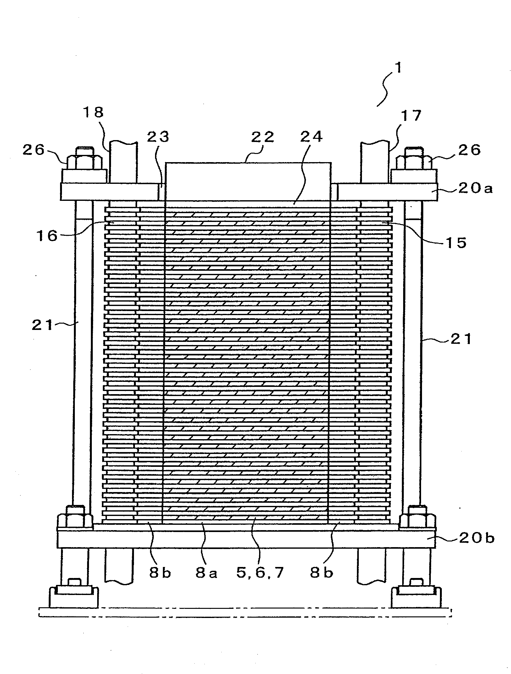
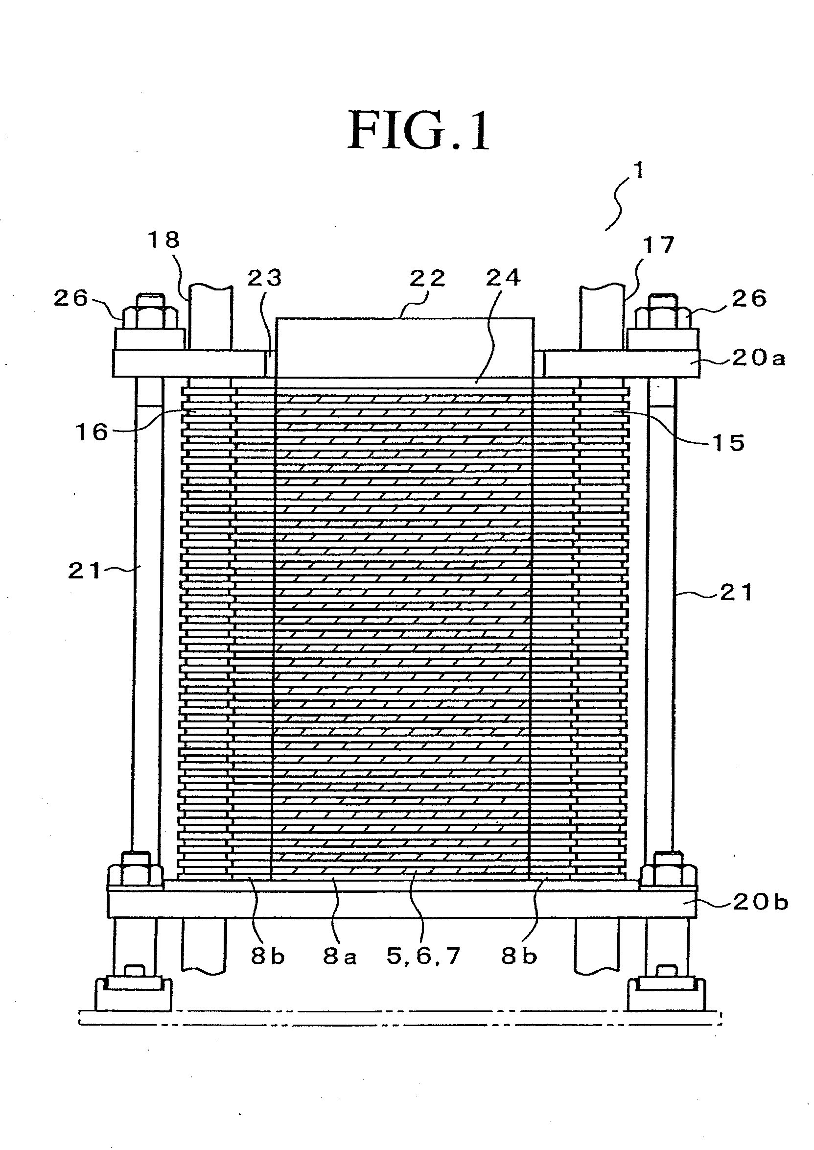
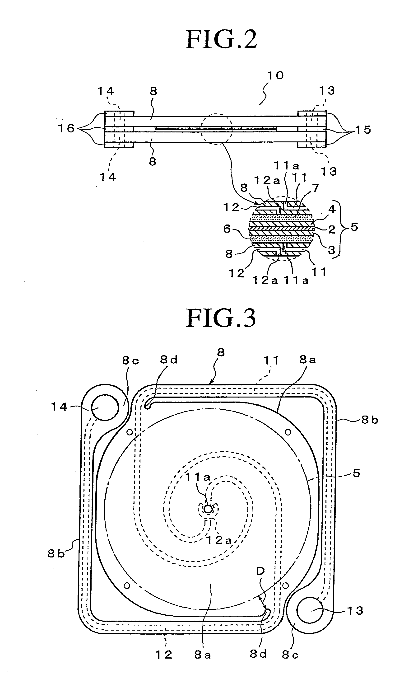
[0035]FIG. 1 shows a configuration of a plate-laminated type solid oxide fuel cell 1 (fuel cell stack 1) according to the present invention; FIG. 2 shows an enlarged view of a part of FIG. 1; and FIG. 3 shows a structure of a separator 8.

[0036]As shown in FIG. 2, a stack unit 10 comprises a circular power generation cell 5 in which a fuel electrode layer 3 and an air electrode layer 4 are arranged on both surfaces of a solid electrolyte layer 2, a fuel electrode current collector 6 on the outer side of the fuel electrode layer 3, an air electrode current collector 7 on the outer side of the air electrode layer 4, and two separators 8 on the outer side of each of the current collectors 6 and 7.

[0037]Among power generating elements mentioned above, the solid electrolyte layer 2 is formed of stabilized zirconia (YSZ) doped with yttria, and the like. The ...


PUM

PropertyMeasurementUnit
shapeaaaaaaaaaa
flexibilityaaaaaaaaaa
elastic deformationaaaaaaaaaa

Abstract

The objective of the invention is to prevent plastic deformation of separators in a heat cycle of the fuel cell, to thereby prevent damage to the power generation cell. A laminated body is formed by alternately laminating power generation cells (5) and separators (8) having reactant gas passages (11 and 12) inside thereof, and a fuel gas manifold and an oxidant gas manifold, which are in communication with the reactant gas passages (11 and 12) of each separator (8) and extending in the laminating direction, are located at a periphery of the laminated body, and a load is applied to the laminated body in the laminating direction. The separator (8) includes: an interconnect section (8a) at a center of which the power generation cell (5) is located; and a pair of arm sections (8b) with an elongated strip shape, each arm section (8b) extending from a rim of the interconnect section (8a), and an end (8c) of each arm section (8b) being connected to the fuel gas manifold or the oxidant gas manifold. The arm section (8b) has flexibility so that it can be deformed in the laminating direction, and the deformation of the arm section (8b) is kept in the range of elastic deformation during the heat cycle.

Description

TECHNICAL FIELD[0001]The present invention relates to a plate-laminated type fuel cell constructed by alternately laminating power generation cells and separators, and more particularly to a structure of the separator.BACKGROUND ART[0002]A plate-laminated type fuel cell is known in the art, which is constructed by alternately laminating separators and power generation cells having a structure in which a solid electrolyte layer made of an oxide ion conductor is sandwiched between an air electrode layer and a fuel electrode layer.[0003]The plate-laminated type fuel cell has a multilayered structure in which each of the power generation cells is formed by laminating a plurality of fuel elements described above, and these power generation cells are also laminated through the separators and conductive members such as current collectors. Therefore, the plate-laminated type fuel cell is required to have excellent adhesiveness between elements thereof for securing stable fuel cell performan...

Claims


Application Information

Patent Timeline
Patent Type & Authority Applications(United States)
IPC IPC(8): H01M8/24H01M2/00
CPCH01M8/0247H01M8/2425Y02E60/50H01M8/248H01M8/2465H01M8/2484
Inventor AKBAY, TANERMIYAZAWA, TAKASHIMURAKAMI, NAOYASUZUKI, TADAHIKO
Owner AKBAY TANER
Why Eureka
Try Eureka