Chain tensioner

a chain tensioner and tensioner technology, applied in the direction of belts/chains/gearings, mechanical instruments, belts/chains/gearings, etc., can solve the problems of reducing the size and weight of the housing. , to achieve the effect of radially expanding the ring portion of the register ring

Inactive Publication Date: 2010-04-15
NTN CORP
View PDF15 Cites 25 Cited by
  • Summary
  • Abstract
  • Description
  • Claims
  • Application Information

AI Technical Summary

Benefits of technology

[0012]To achieve this object, the present invention provides a chain tensioner comprising a cylindrical housing having an open front end and a closed rear end, a plunger slidably mounted in the housing, a return spring mounted in the housing and biasing the plunger outwardly of the housing, wherein the plunger defines a pressure chamber in the housing, the housing being formed with an oil supply passage communicating with the pressure chamber, a check valve provided at an oil outlet of the oil supply passage to prevent backflow of oil in the pressure chamber into the oil supply passage, wherein a circumferentially extending ring receiving groove is formed in an inner periphery of the housing near the open end thereof, and a cutout is formed in the open end of the housing so as to cross the ring receiving groove, and a register ring comprising an elastically radially deformable ring portion received in the ring receiving groove and having circumferentially spaced ends, and a pair of operating pieces formed by bending the respective ends of the ring portion in an axial direction and received in the cutout, wherein a plurality of circumferential grooves are formed in an outer periphery of the plunger at axially equal intervals, each of the circumferential grooves comprising a tapered surface of which the diameter gradually decreases toward a front end of the plunger, and an engaging surface extending radially outwardly from the small-diameter front end of the tapered surface, the register ring being engageable in and radially pressed against any of the circumferential grooves, the ring receiving groove having a rear stopper surface, wherein when the plunger is pushed into the housing, the register ring is configured to be trapped between the stopper surface of the ring receiving groove and the engaging surface of one of the circumferential grooves, thereby preventing any further retraction of the plunger.
[0014]The pair of operating pieces may be circular in shape, in the shape of a water drop, arcuate in shape, angular U-shaped or V-shaped, or may be straight members extending in an axial direction, or straight members extending obliquely radially outwardly from the ring portion. By bringing the opening / closing pieces at the tip of a snap ring removing tool into engagement with the operating pieces, which may be of any of the above-described shapes, from radially outside the housing, it is possible to reliably push the operating pieces apart from each other, thereby radially expanding the ring portion of the register ring.
[0015]With this arrangement, the circumscribed circle of the register ring has a smaller diameter than that of the conventional register ring in which the operating pieces extend in the same axial direction from the respective radially outer ends of extensions extending in the tangential directions of the ring portion of the register ring so as to cross each other. This makes it possible to minimize the size and weight of the housing.

Problems solved by technology

Oil supplied into the pressure chamber through the oil supply passage dampens the pushing force applied to the plunger from the chain.
When the engine is restarted in this state, the chain tends to slacken markedly.
But immediately after the engine has started, an oil pump for supplying oil into the pressure chamber is unable to deliver a sufficient amount of oil and thus unable to supply a sufficient amount of oil into the pressure chamber, of which the volume is increasing rapidly.
Thus, immediately after the start of the engine, this chain tensioner cannot sufficiently perform its hydraulic dampening function.
This may cause flapping of the chain or skipping of a tooth or two of the sprockets.
If the outer diameter of the housing is smaller than the diameter of this imaginary circle, the operating pieces protrude from the radially outer surface of the housing, and may interfere with engine parts when mounting and dismounting the chain tensioner to and from the engine, thus making it difficult to mount and dismount the chain tensioner.

Method used


Image

  • Chain tensioner
  • Chain tensioner
  • Chain tensioner

Examples


Embodiment Construction

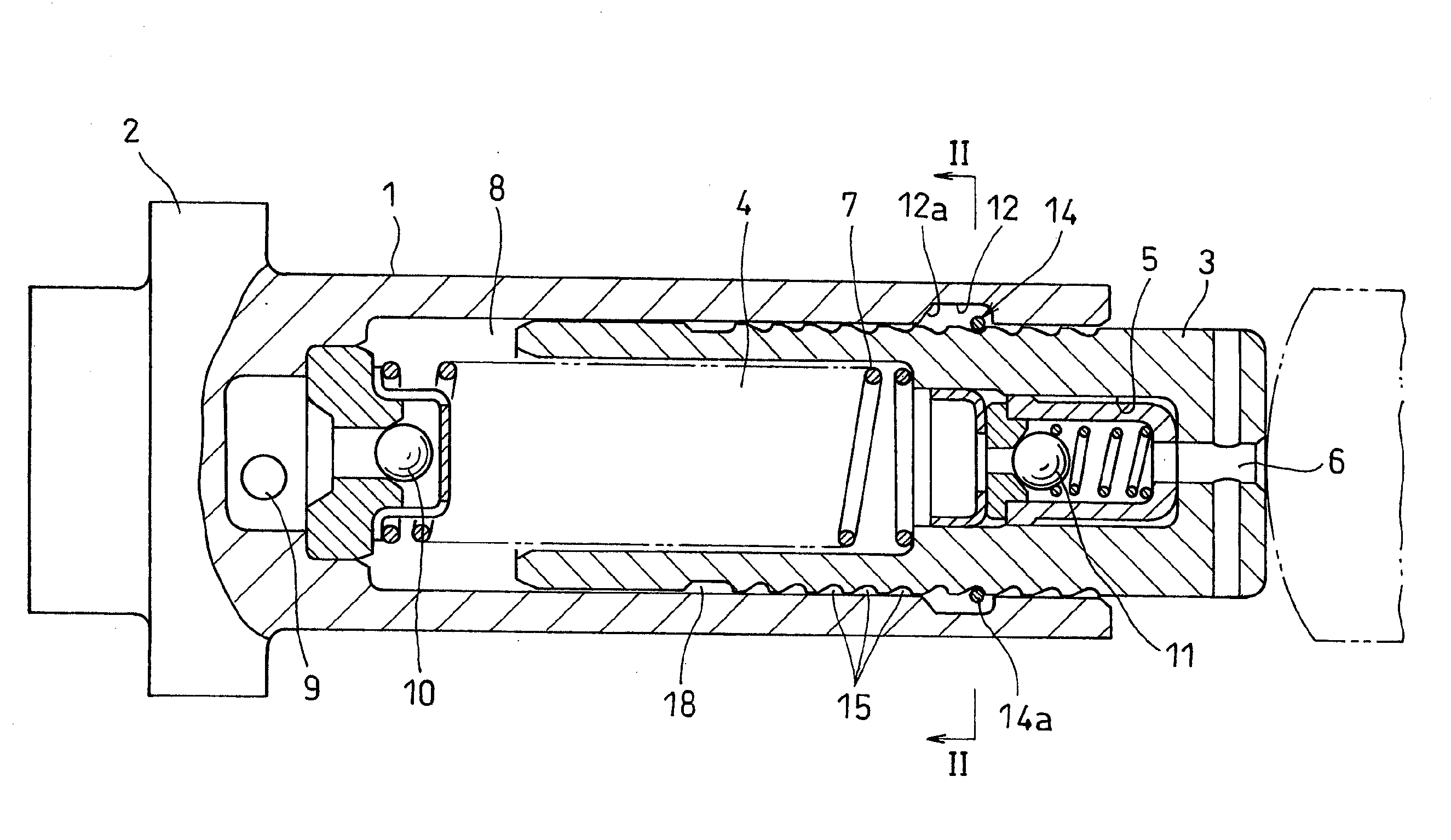
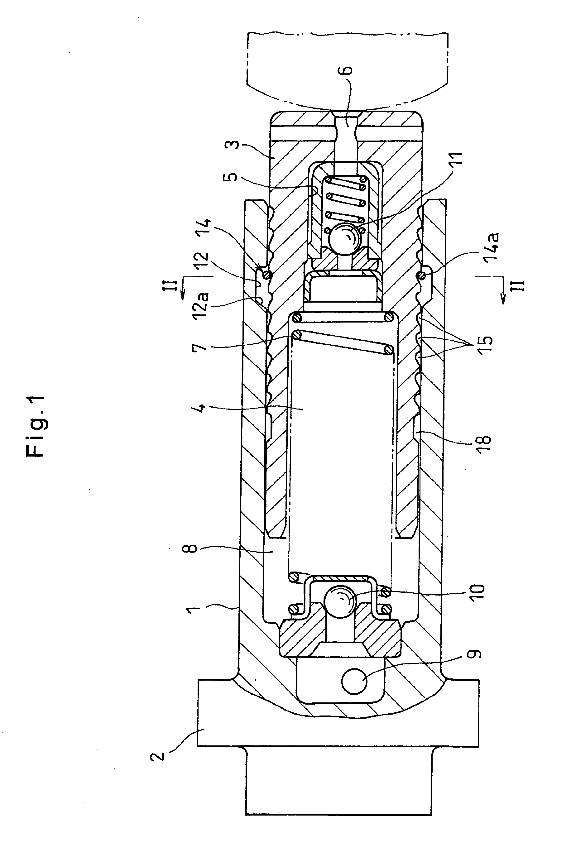
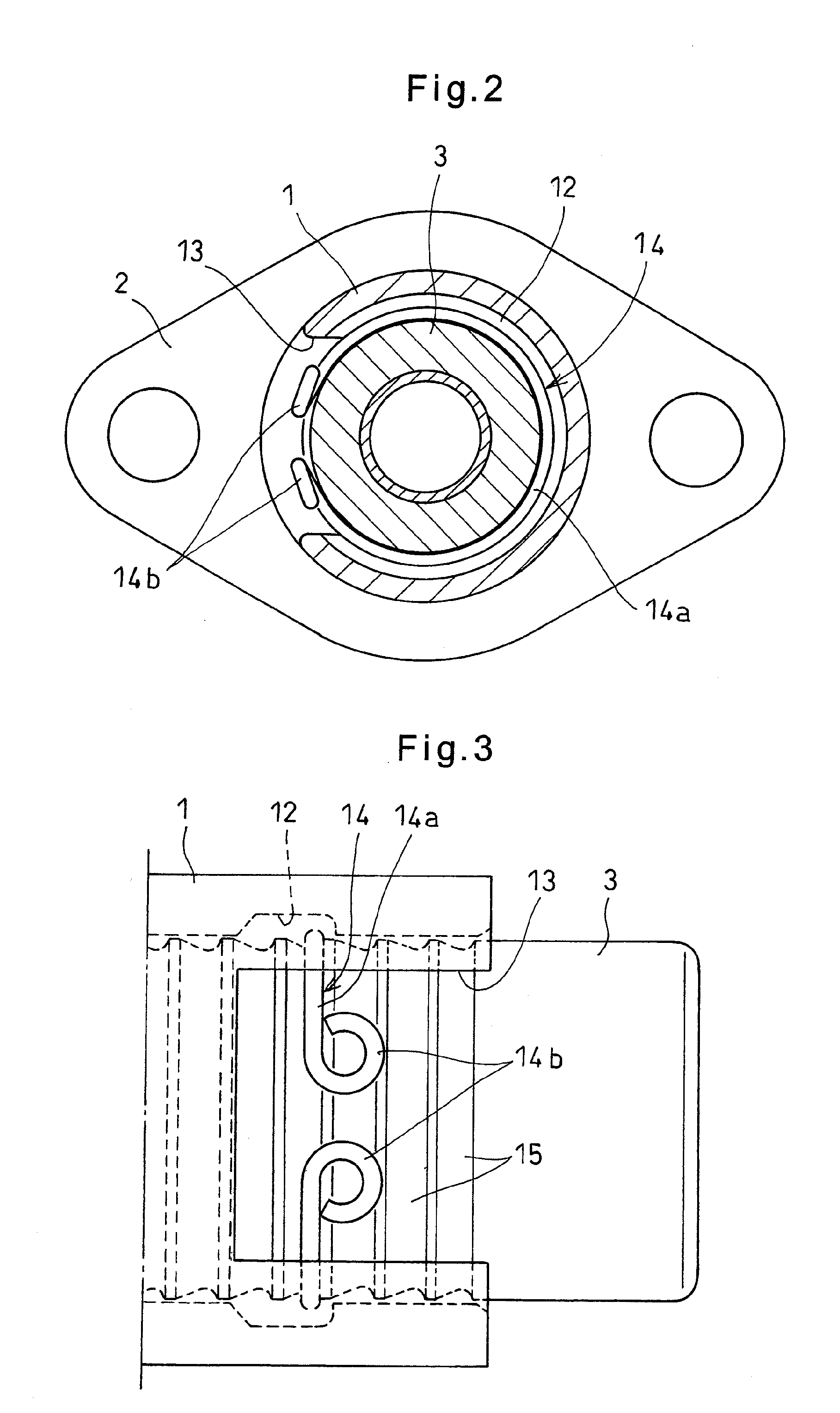
[0026]Now referring to the drawings, the embodiment of the present invention is described. As shown in FIG. 1, the chain tensioner of the embodiment comprises a cylindrical housing 1 having closed and open ends, and having a flange 2 formed on the outer periphery thereof and configured to be mounted to an engine cover.

[0027]A plunger 3 is slidably mounted in the housing 1. The plunger 3 has a spring mounting bore 4 having a rear open end and a front closed end, a valve mounting hole 5 formed in the front closed end of the spring mounting bore 4, and a pressure release hole 6 through which the valve mounting hole 5 communicates with the exterior of the housing 1. A return spring 7 is mounted between the closed end of the spring mounting bore 4 and the closed end of the housing 1. The return spring 7 biases the plunger 3 outwardly of the housing 1.

[0028]In the closed end wall of the housing 1, an oil supply passage 9 is formed which communicates with a pressure chamber 8 defined in th...


PUM


Abstract

A chain tensioner includes a housing and a plunger slidably mounted in the housing. A ring receiving groove is formed in the inner periphery of the housing in which a register ring is received. The register ring is engageable in any of a plurality of circumferential grooves formed in the outer periphery of the plunger at equal axial intervals. When the plunger is pushed into the housing, the register ring is trapped between a stopper surface of the ring receiving groove and an engaging surface of one of the circumferential grooves, thereby preventing further retraction of the plunger. The register ring includes a ring portion received in the ring receiving groove and having circumferentially spaced ends, and a pair of operating pieces formed by bending the opposed ends of the ring portion to extending in the same axial direction.

Description

BACKGROUND OF THE INVENTION[0001]This invention relates to a chain tensioner for keeping constant the tension of a timing chain or a timing belt for driving camshafts.[0002]A chain transmission device is a device for transmitting the rotation of a crankshaft to camshafts through a timing belt or a timing chain (hereinafter referred only to a chain; but it should be understood that as used herein, the word “chain” encompasses a belt too). The chain transmission device includes a pivotable chain guide kept in contact with the slack side of the chain, and a chain tensioner which applied an adjusting force to the chain through the chain guide, thereby keeping constant the tension of the chain.[0003]One known chain tensioner comprises a housing defining a cylinder chamber, a plunger mounted in the cylinder chamber, and a return spring mounted in the cylinder chamber and biasing the plunger outwardly of the housing. An oil supply passage is formed in the housing which communicates with a ...

Claims


Application Information

Patent Timeline
Patent Type & Authority Applications(United States)
IPC IPC(8): F16H7/08
CPCF16H7/0848F16H2007/0806F16H2007/0859F16H2007/0853F16H2007/0855F16H2007/0814
Inventor ONIMARU, KOUICHIRYOUNO, YOSHIAKI
Owner NTN CORP
Why Eureka
Try Eureka