Energy saving system

a technology of energy saving and energy saving, applied in the field of energy saving systems, can solve the problems of imposing burden on users, new cost and trouble, and high cost of sensors and their installation expenses, and achieve the effects of promoting energy/electric power saving, saving energy/electric power, and conducting the attempt more easily and more reliably

Inactive Publication Date: 2010-04-15
HITACHI LTD
View PDF22 Cites 6 Cited by
  • Summary
  • Abstract
  • Description
  • Claims
  • Application Information

AI Technical Summary

Benefits of technology

[0026]The invention can provide a system that can automatically judge the existence/absence of personnel by only external database information for managing position information of the personnel typified by a seat occupation management system irrespective of the existence/absence of sensors and the number of the sensors, automatically turns off the power

Problems solved by technology

Therefore, this system involves the problems that the cost of the sensors and their installation expenses are extremely high.
To reduce the number of installation positions and to save the trouble and cost of the installation, novel substitute means must be prepared and this again invites new cost and trouble while imposing the burden to the users.
When the number of personnel who

Method used


Image

  • Energy saving system
  • Energy saving system
  • Energy saving system

Examples


embodiment 1

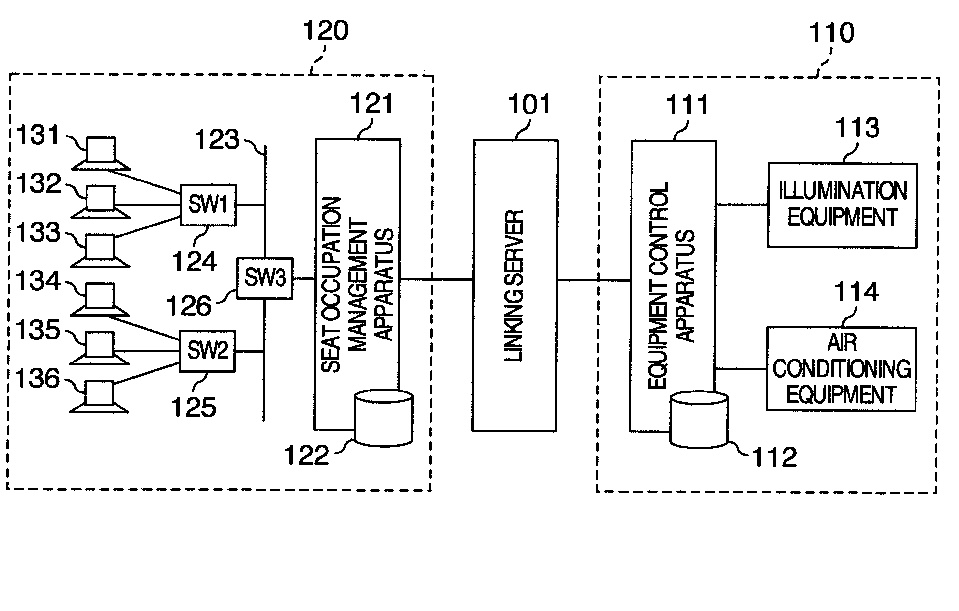
[0045]FIG. 1 is a basic system construction view for executing an embodiment of the invention. In the drawing, reference numeral 110 denotes an equipment control system. This system includes illumination equipment such as fluorescent lamps, air conditioning equipment 114 such as air conditioners, an equipment control apparatus 111 for controlling these kinds of equipment and a database 112 for managing information such as an the operating conditions of the equipment appliances and their installation positions. The equipment may well be information apparatuses such as printers and information appliances other than the illumination appliances and air conditioning appliances.

[0046]The equipment control system 110 keeps the information of the equipment appliances the system manages and controls by itself in the database 112 and access can be made from outside to the information of the database 112 through an interface provided to the equipment control apparatus 111. The system can also ...

embodiment 2

[0064]Next, an energy saving linking system according to another embodiment of the invention will be described. The embodiment will be explained by the additional explanation to Embodiment 1.

[0065]FIG. 8 is a logical structural view showing the functional construction of the linking server 101 explained with reference to FIG. 6 and a display information generation unit 801 and a display control unit 802 are added to this structural view. The display information generation unit 801 has the functions of receiving the calculation result information from the calculation unit 604 and converting the information into the display information that is easily comprehensive to the users. It has the functions of generating the display information shown in later-appearing FIGS. 12 and 13. The display control unit 802 has the functions of controlling the display information generated by the display information generation unit 801 in accordance with the request from the users.

[0066]FIG. 9 shows the...

embodiment 3

[0075]Lastly, an energy saving linking system according to still another embodiment will be hereinafter described. The embodiment will be explained by the additional explanation to Embodiments 1 and 2.

[0076]FIG. 14 is a structural view when a report processing unit 1401 is added to the logical structural view of FIG. 8 that shows the functional construction of the linking server 101. The report processing unit 1401 has the function of sending a message representing the calculation result from the calculation unit 604 to the information terminal capable of receiving the message.

[0077]FIG. 15 shows the processing step executed by the calculation unit 604 of the linking server 101. This processing step judges whether or not each seat occupying personnel exists in the overtime work area on the basis of the seat occupying personnel information from the seat occupation management system 120, and sends the information of the overtime work area and the message urging the movement when the p...


PUM


Abstract

An energy saving system acquires seat occupation information from a database of a seat occupation management system, detects equipment appliances of the places at which personnel are not seated, on the basis of the seat occupation information and transmits control information based on the detection result to an equipment control system so that unnecessary equipment appliances of the places where the personnel do not exist can be turned off. The energy saving linking system executes a processing for calculating optimal position and range in accordance with the seat occupation information, calculates an area providing the highest movement efficiency to overtime personnel and displays the calculation result.

Description

INCORPORATION BY REFERENCE[0001]The present application claims priority from Japanese application JP 2008-265879 filed on Oct. 15, 2008, the content of which is hereby incorporated by reference into this application.BACKGROUND OF THE INVENTION[0002]This invention relates to a linking system of an equipment control system for environmental equipment appliances such as air conditioning equipment or illumination equipment in accordance with seat occupying positions of seat occupying personnel with a seat allocation system capable of calculating seat allocation of persons moving in accordance with a certain object and displaying the seats allocated. More particularly, the invention relates to a control system that links (combines) these systems to one another and promotes saving of energy and resources of the equipment appliances.[0003]Innovation has taken place in recent years in the work styles of enterprises with the progress of network systems and with the progress of communication ...

Claims


Application Information

Patent Timeline
IPC IPC(8): G06F1/32G05D23/19F24F11/02G06Q50/00G06Q50/16H04L12/28H04M11/00H04Q9/00
CPCF24F11/0034F24F2011/0075G06Q10/02G05B2219/2642G05B15/02F24F11/30F24F2120/10F24F11/46F24F11/66
Inventor KAKIUCHI, HIROYUKI
Owner HITACHI LTD
Why Eureka
Try Eureka