
Temperature compensated density sensing process and device

a density sensing and temperature compensation technology, applied in the field of density-based sensing, can solve the problems of limiting the applicability of this approach, affecting the accuracy of prior art methods for different fluids, and being susceptible to failur

Inactive Publication Date: 2010-04-22
LAYNE CHRISTENSEN COMPANY
View PDF3 Cites 22 Cited by
  • Summary
  • Abstract
  • Description
  • Claims
  • Application Information

AI Technical Summary

Benefits of technology

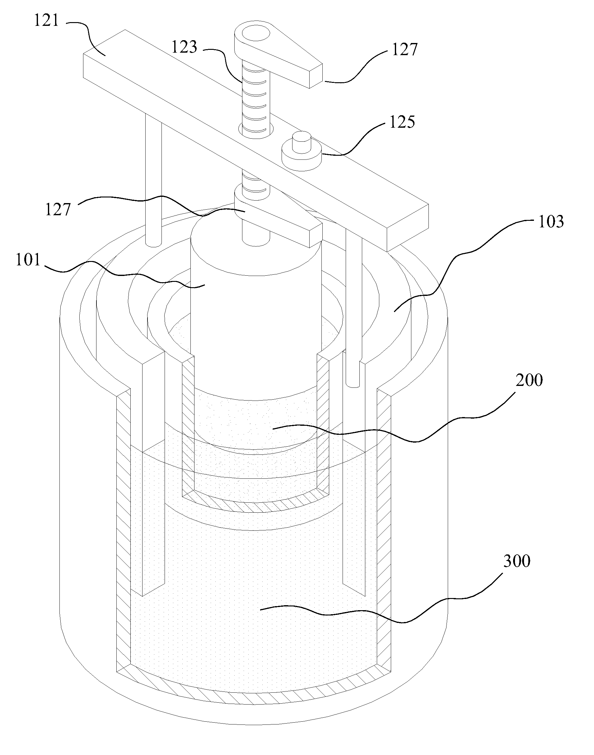
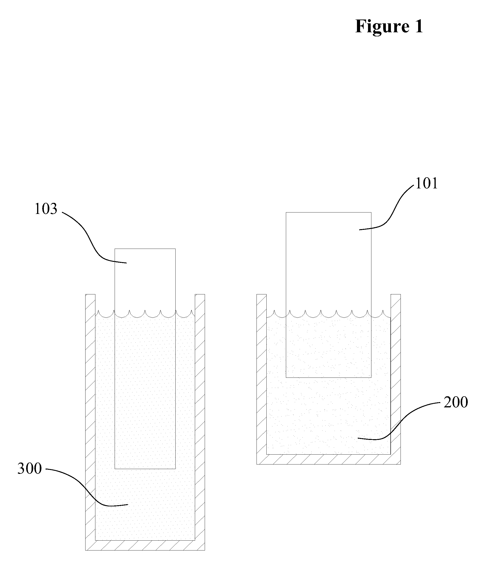
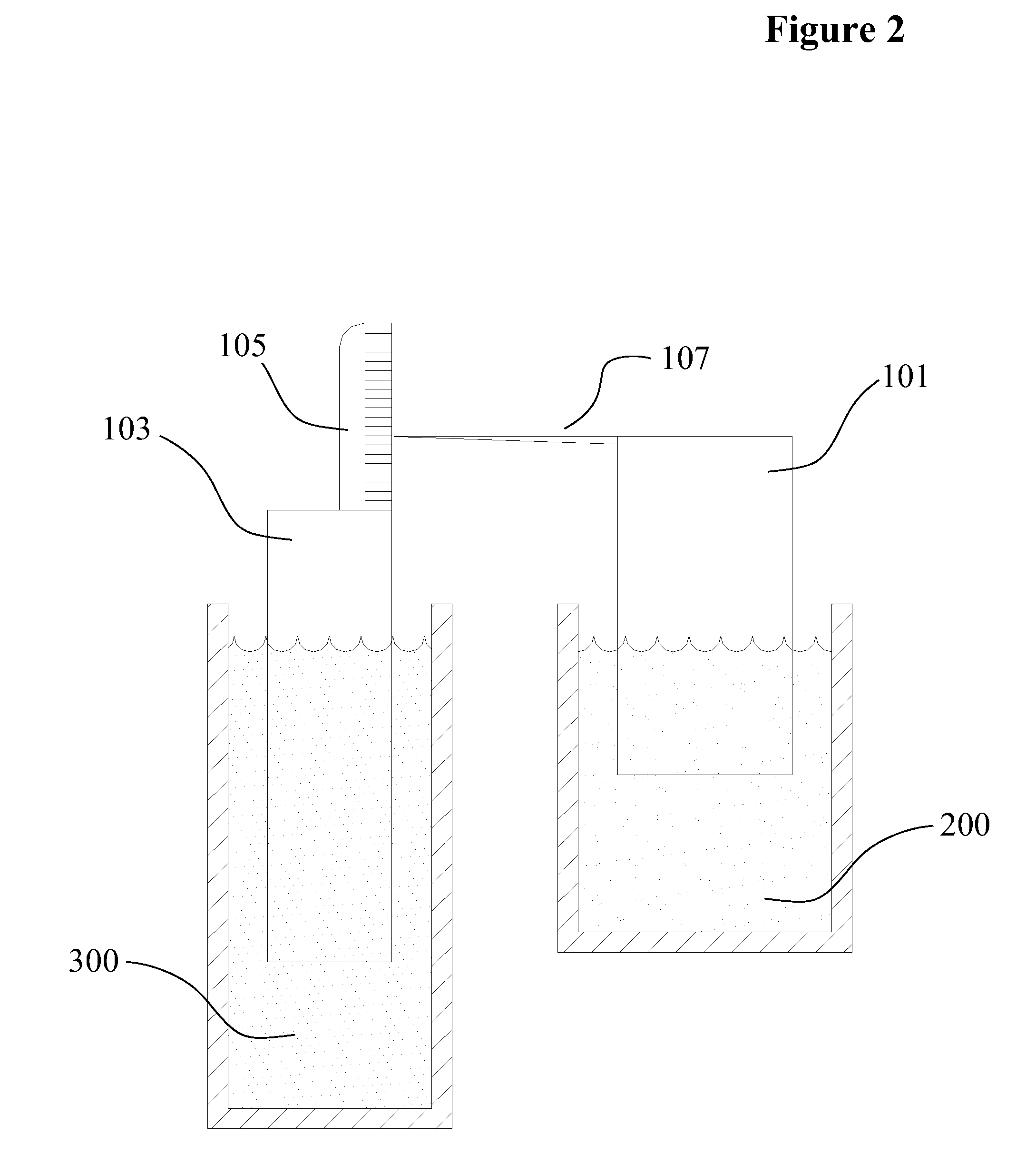
The present invention provides a density sensing process and device that can sense the density of a fluid while compensating for changes in fluid temperature. This is achieved by using buoyant floats that are geometrically configured and weighted so that they rise and fall concurrently with temperature change. The floats are designed to indicate changes in the density of the fluid due to variations in the concentration of solids (TDS) in the fluid. The invention does not require complicated electronics or other external means to sense the TDS while compensating for temperature effects. The sensing device is simple and cost-effective. The technical effects of the invention include the ability to accurately measure the density of a fluid and to monitor, switch, and control processes based on changes in the fluid density.

Problems solved by technology

This approach is accurate only over small temperature ranges and is susceptible to failure due to electrolysis or corrosion of the bimetallic component.
As a result, this method of the prior art will generally not be accurate for different fluids.
This approach is accurate only over small temperature ranges due to the difficulty of accurately matching the thermal properties of solid and liquid materials.
Further, the float material of choice for one fluid generally will not be applicable for another fluid, limiting the applicability of this approach.

Method used


Image

  • Temperature compensated density sensing process and device
  • Temperature compensated density sensing process and device
  • Temperature compensated density sensing process and device

Examples


Embodiment Construction

[0021]The making and using of the presently preferred embodiments are discussed in detail below. It should be appreciated, however, that the present invention provides many applicable inventive concepts that can be embodied in a wide variety of specific contexts. The specific embodiments discussed are merely illustrative of specific ways to make and use the invention, and do not limit the scope of the invention. The present invention will be described with respect to preferred embodiments in a specific context, namely as a device and process for TDS measurement and process control based on the density / specific gravity of a fluid with potentially varying TDS as well as temperature. The invention may also be applied, however, to other situations wherein density / specific gravity measurement / control issues are advantageous.

[0022]The device of the present invention employs buoyancy phenomenon to reflect the TDS via density of a subject fluid. The phenomenon is often referred to as the Ar...


PUM

PropertyMeasurementUnit
temperatureaaaaaaaaaa
temperaturesaaaaaaaaaa
Specific Gravityaaaaaaaaaa

Abstract

A total dissolved solids measurement process and device are provided that facilitates total dissolved solids sensing of a subject fluid via relative buoyancy levels of separate float bodies; one buoyed by the subject fluid of varying total dissolved solids and temperatures and another buoyed by a reference fluid of constant total dissolved solids but of a varying temperature matching the subject fluid. The equal temperature baths of the subject fluid and the reference fluid as well as geometrical shape and weighting of the floats conveys the total dissolved solids as the difference in buoyancy levels of the floats. This difference in buoyancy levels is of further benefit for activation of sundry controls.

Description

CROSS-REFERENCE TO RELATED APPLICATIONS[0001]This non-provisional application claims priority based upon prior U.S. Provisional Patent Application Ser. No. 61 / 097,046 filed Sep. 15, 2008 in the name of James Jeffrey Harris, entitled “Specific Gravity Switch,” the disclosure of which is incorporated in its entirety by this reference as if fully set forth herein.BACKGROUND OF THE INVENTION[0002]The present invention concerns density-based sensing of total dissolved solids (TDS) of a fluid; especially those fluids wherein the density varies both due to TDS and temperature. The prior art primarily employs one of three methods for sensing the TDS of fluids; electric resistance, nuclear properties or density-based methods. The density-based approach is the simplest and most economical.[0003]Density methods require temperature corrections to accurately relate density measurements to TDS values. The prior art employs various means for such corrections; some corrections are simply performed ...

Claims


Application Information

Patent Timeline
Patent Type & Authority Applications(United States)
IPC IPC(8): G01N9/00
CPCG01N9/12G01N15/06G01N9/36G01N9/18
Inventor HARRIS, JAMES JEFFREY
Owner LAYNE CHRISTENSEN COMPANY
Learn More