VSA gas concentrator using a reversing blower

a gas concentrator and blower technology, applied in the direction of separation process, dispersed particle separation, chemistry apparatus and processes, etc., can solve the problems of significant power and potentially elaborate machinery for effective gas separation, difficulty, and undesirable liquefaction, and achieve simple configuration and operation. simple

Inactive Publication Date: 2010-04-22
PACIFIC CONSOL INDS
View PDF8 Cites 44 Cited by
  • Summary
  • Abstract
  • Description
  • Claims
  • Application Information

AI Technical Summary

Benefits of technology

The technical effect of this patent is that it provides a gas separator that has two main benefits: it is both compact and easy to operate with minimal parts. This makes it ideal for use in various applications where space or simplicity are important factors.

Problems solved by technology

This patent describes techniques for separating gases from mixtures containing several gases. However, existing methods like crystallization and distillation may not work well for all gases, especially if their boiling point is close to the surrounding environment's temperature. Other methods like membrane technology and pressure swing adsorption (both PSA and VS A) exist, but they too may struggle with some gases due to low solubility or high energy requirements. Therefore, there is a technical problem of providing efficient and compact devices for separating specific gases without requiring complex valve and pneumatic components.

Method used


Image

  • VSA gas concentrator using a reversing blower
  • VSA gas concentrator using a reversing blower

Examples


Embodiment Construction

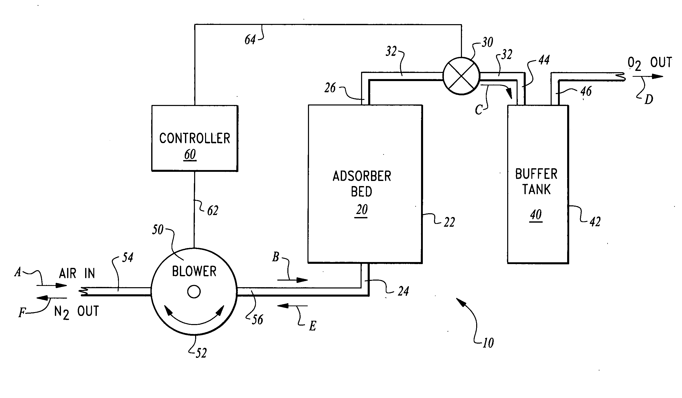
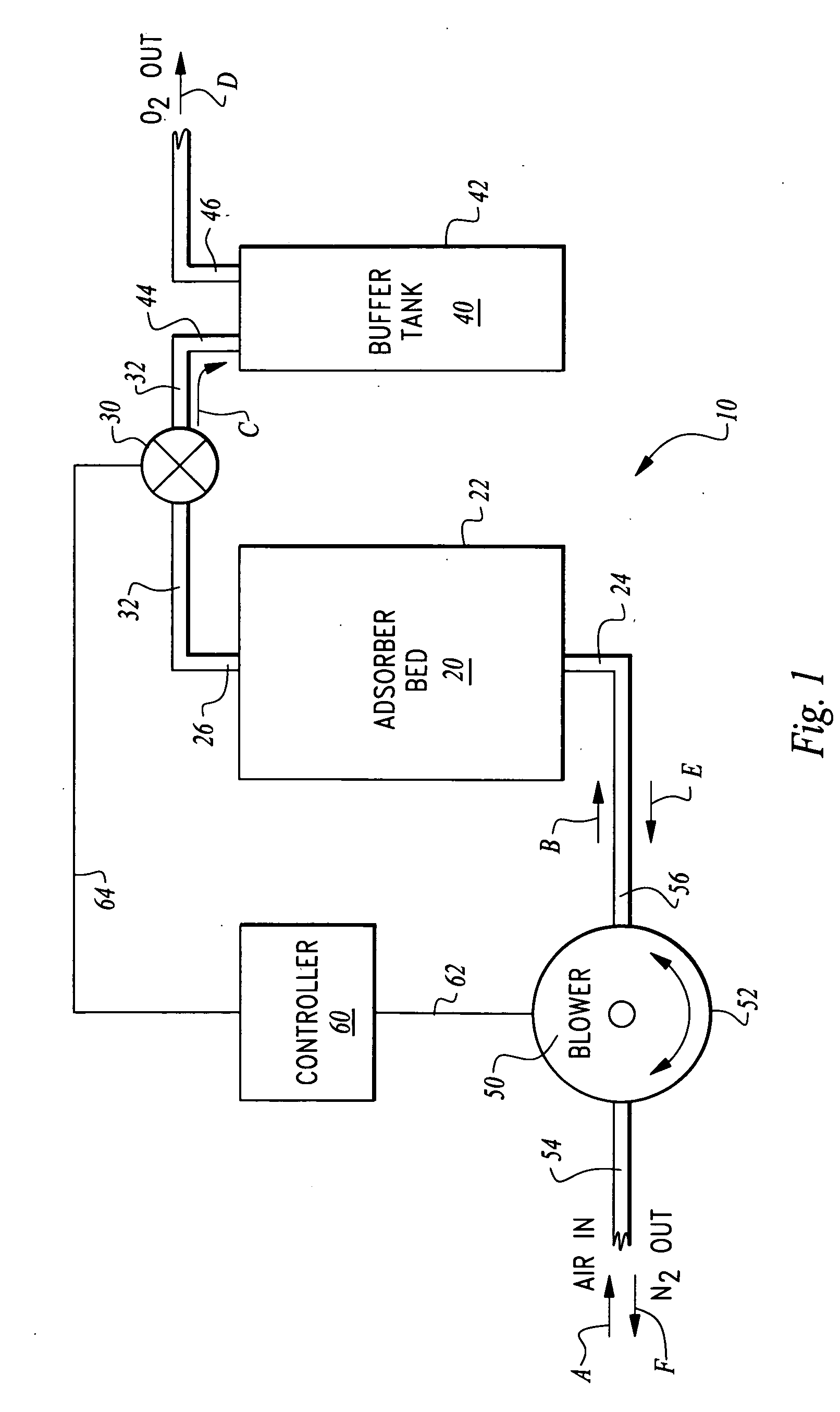
[0025]Referring to the drawings, wherein like reference numerals represent like parts throughout the various drawing figures, reference numeral 10 (FIG. 1) is directed to an oxygen separator configured to separate / concentrate oxygen from air in a preferred embodiment of this invention. While the invention is illustrated in this embodiment as being configured to separate oxygen from air, through this selection of an appropriate adsorbent material other gases could be preferentially separated from gas mixtures utilizing the same or an appropriately modified system.

[0026]In essence, and with particular reference to FIG. 1, basic details of the oxygen separator 10 described in the preferred embodiment of this invention are disclosed. The oxygen separator 10 includes an adsorber bed 20 including an adsorber material therein which preferentially adsorbs nitrogen, CO2 and water over oxygen. A valve 30 is located downstream of the adsorber bed 20. A buffer tank 40 is provided downstream of ...


PUM

PropertyMeasurementUnit
Timeaaaaaaaaaa
Pressureaaaaaaaaaa
Flow rateaaaaaaaaaa

Abstract

The concentrator separates one gas (i.e. oxygen) from a gas mixture (i.e. air) through the process of vacuum swing adsorption (VSA). An adsorber material is located within an adsorber bed. The adsorber bed has an inlet and an outlet. A valve is located downstream of the outlet. A pump, such as a blower, is provided upstream of the adsorber bed to drive a mixed gas into the adsorber bed. The adsorber material selectively adsorbs an undesirable gas (i.e. nitrogen) leaving a desirable gas (i.e. oxygen) from the mixture to pass through the outlet and through the valve. The pump is reversible. When the adsorber material becomes saturated, the pump is reversed and a vacuum is drawn on the adsorber bed. The valve is closed while the pump is operating in this reverse direction. After the adsorber material has desorbed the undesirable gas, the pump again reverses and the cycle is repeated.

Description


Claims


Application Information

Patent Timeline
Owner PACIFIC CONSOL INDS
Why Eureka
Try Eureka