Lever type output shaft locking device

a technology of output shaft and locking device, which is applied in the direction of portable power-driven tools, manufacturing tools, portable drilling machines, etc., can solve the problems of not being able to actually output torque to drill holes, the rechargeable battery cannot provide limited voltage, and the drill cannot provide torque to drill holes. to achieve the effect of reliable locking featur

Inactive Publication Date: 2010-04-22
TOP GEARBOX IND
View PDF25 Cites 2 Cited by
  • Summary
  • Abstract
  • Description
  • Claims
  • Application Information

AI Technical Summary

Benefits of technology

[0011]The output shaft locking device of the present invention provides a reliable locking feature even if the positioning ring and the output shaft does not precisely share a common axis.

Problems solved by technology

However, the rechargeable battery can only provide limited voltage which cannot drive the power drill for a longer time and it takes a lot of time to recharge the battery.
This makes the bit to rotate without output torque so that the drill cannot actually output torque to drill a hole.
This is not convenient for the users.
Nevertheless, the positioning ring and the output shaft may not be precisely installed to have the same axis; the beads cannot be pushed evenly, so that the locked status is not reliable.

Method used


Image

  • Lever type output shaft locking device
  • Lever type output shaft locking device
  • Lever type output shaft locking device

Examples


Embodiment Construction

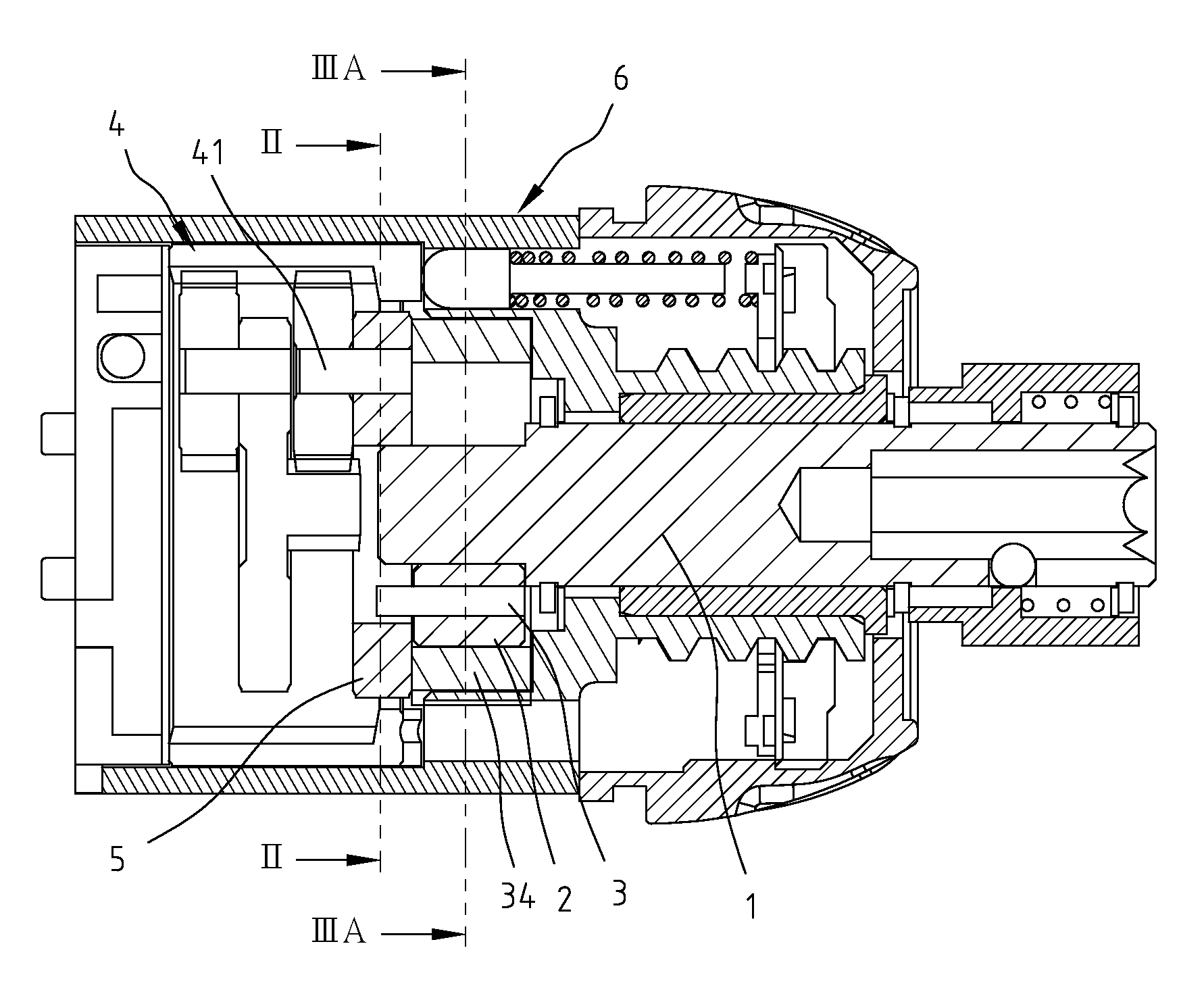
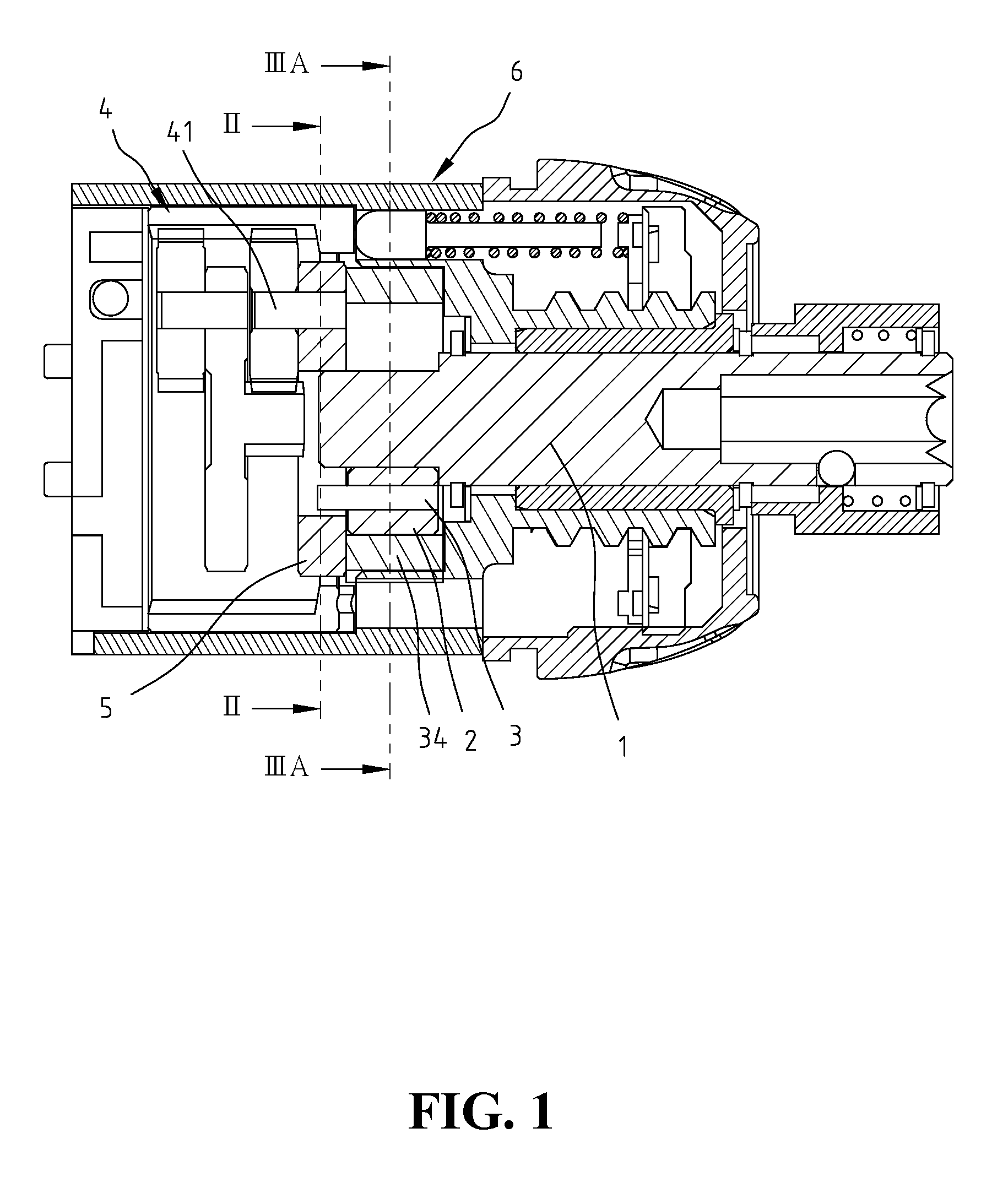
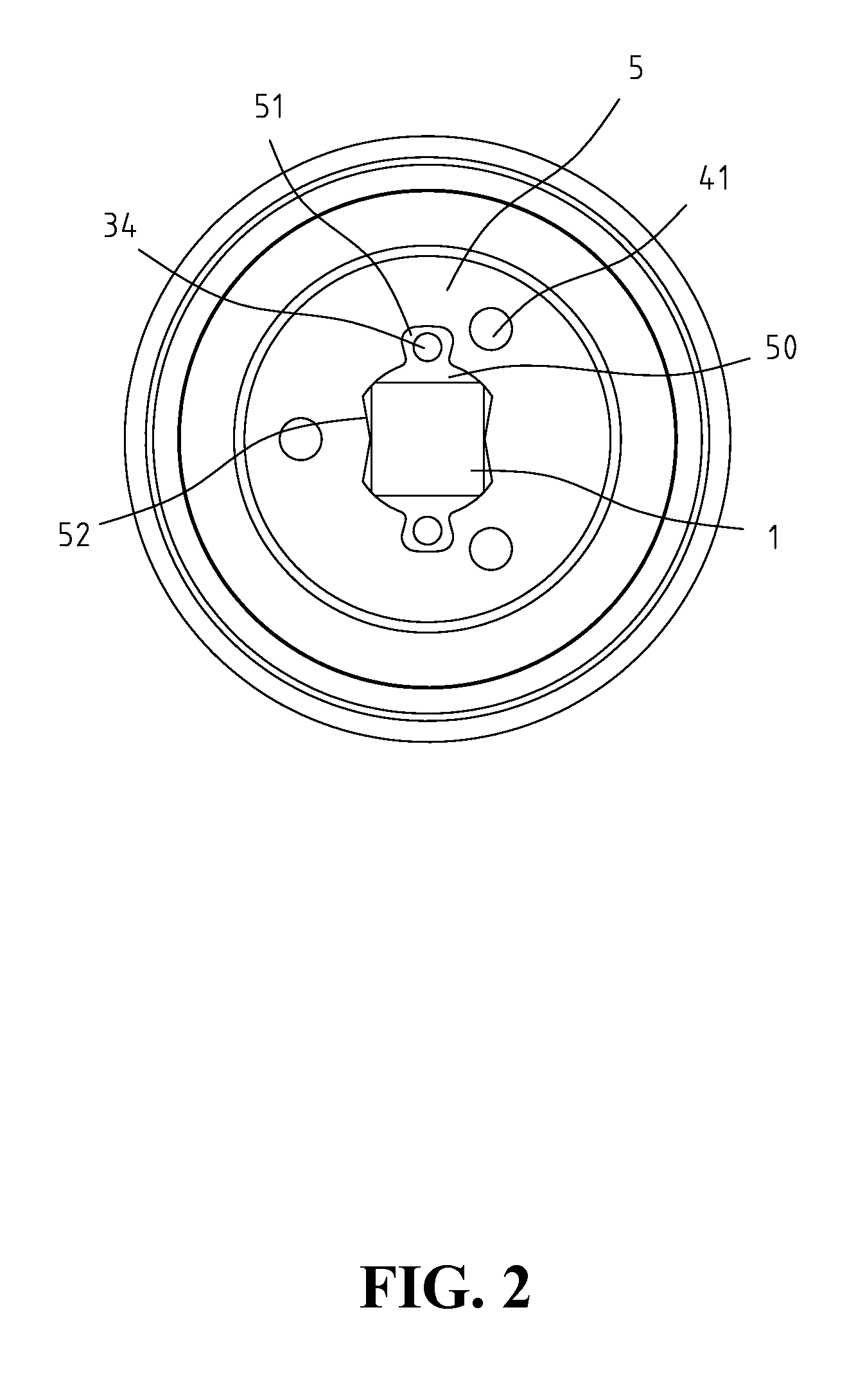
[0019]With reference to the drawings and in particular to FIGS. 1 and 2, an output shaft locking device in accordance with the present invention comprises an output shaft 1 which is received in a casing 6 of the power tool and bearings are mounted to the output shaft 1 which is freely rotatable. The front end of the output shaft 1 extends out from the casing 6 so as to be connected with tool bits such as screw bits and drills. A positioning ring 2 and at least two activation members 3 are received in the casing 6. A reduction gear set 4 is located in a rear end of the casing 6 and connected with a motor (not shown). The gear set 4 further is connected to a driving disk 5 by pins 41 and the driving disk 5 has a central hole 50 which includes two recesses 51 defined in an inner periphery thereof. The two recesses 51 are separated by 180 degrees of angular distance. Two pie-shaped protrusions 52 extend inward from the central hole 50 and located at 90 degrees of angular distance from t...


PUM

PropertyMeasurementUnit
poweraaaaaaaaaa
electric poweraaaaaaaaaa
voltageaaaaaaaaaa

Abstract

An output shaft locking device for a power tool includes a positioning ring having a circular inner periphery and an output shaft extends through the positioning ring. Two activation members are between the positioning ring and the output shaft. Each activation member has a first protrusion on a central portion of one side thereof, and a second protrusion and a third protrusion are on two ends of the other side thereof. The first protrusions of the two activation members contact the output shaft, and the second protrusions and the third protrusions face the circular inner periphery of the positioning ring. When the output shaft rotates clockwise, the activation members are pushed outward and the second protrusions contact the positioning ring which applies a reaction force to pivot the activation members so that the third protrusions contact the positioning member to lock the output shaft from rotation.

Description

BACKGROUND OF THE INVENTION[0001]1. Field of the Invention[0002]The present invention relates generally to an output shaft locking device for a power tool, and more particularly, to an output shaft locking device which locks the output shaft when no power is supplied.[0003]2. The Prior Arts[0004]A conventional power tool such as a power drill is powered by electric power which can be supplied by plugging with the receptacles, rechargeable battery or a switching device for employing either of the two aforementioned ways to provide power. When there is power supplied, the power drill can be directly connected with the power source such as the AC power. When there is no AC power available, or the cord is too short to reach the receptacles, the rechargeable battery is an ideal solution. However, the rechargeable battery can only provide limited voltage which cannot drive the power drill for a longer time and it takes a lot of time to recharge the battery. When no power can be used, the ...

Claims


Application Information

Patent Timeline
Patent Type & Authority Applications(United States)
IPC IPC(8): B23Q5/00
CPCB23B45/008B25F5/001B25B21/00
Inventor CHIU, JUNG-CHING
Owner TOP GEARBOX IND
Why Eureka
Try Eureka