Charge method and device of battery for electric motor vehicle

Active Publication Date: 2010-04-22
MAZDA MOTOR CORP
View PDF3 Cites 51 Cited by
  • Summary
  • Abstract
  • Description
  • Claims
  • Application Information

AI Technical Summary

Benefits of technology

[0006]An object of the present invention is to provide a charge method of a battery for an electric motor vehicle and a charge device of a battery for an electric motor vehicle which can complete the warm-up of the battery by the estimated driving-start t

Problems solved by technology

However, the number of the electric motor vehicles spreading is still small, so there are not sufficiently many places where the outside electric source is located.
Accordingly, there is a concern that the charging of the battery by the outside electric source could not be necessarily conducted properly when the residual charge quantity of the battery becomes small and the charging becomes necessary.
Meanwhile, there is a concern that the motor of the electric motor vehicle could not be started properly in a cold season unless the battery is warmed up, so that the vehicle's driving would not be started prompt

Method used


Image

  • Charge method and device of battery for electric motor vehicle
  • Charge method and device of battery for electric motor vehicle
  • Charge method and device of battery for electric motor vehicle

Examples


Example

Embodiment 1

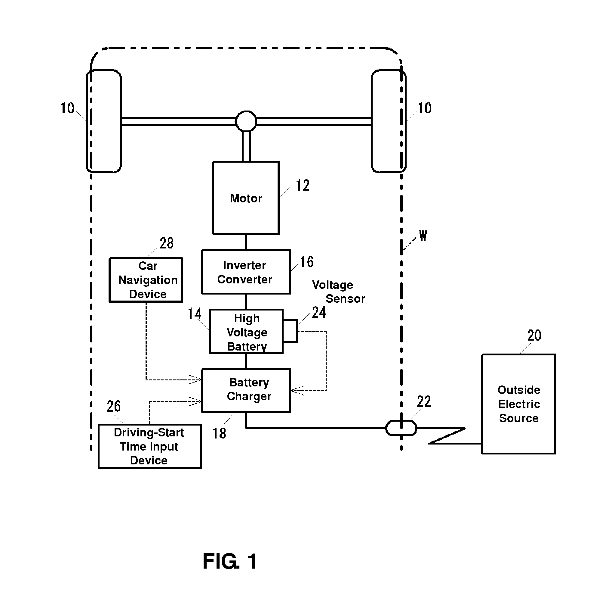
[0030]FIG. 1 is a diagram schematically showing constitution of an electric motor vehicle W which executes a charge method of a battery for the electric motor vehicle according to a first embodiment of the present invention.

[0031]As shown in FIG. 1, the electric motor vehicle W is a vehicle in which wheels 10 are driven by a motor 12, and installs a high-voltage battery 14 to supply an electric power to the motor 12 therein. The motor 12 is coupled to the battery 14 via an inverter converter 16. The inverter converter 16 supplies the electric power to the motor 12 with conversion of the direct current from the battery 14 to the alternating current, and also supplies the electric power to the battery 14 with conversion of the alternating current which is generated by the motor 12, which functions as a generator during a vehicle deceleration, to the alternating current.

[0032]The battery 14 is charged not only by the motor 12 which functions as the generator but by a batter...

Example

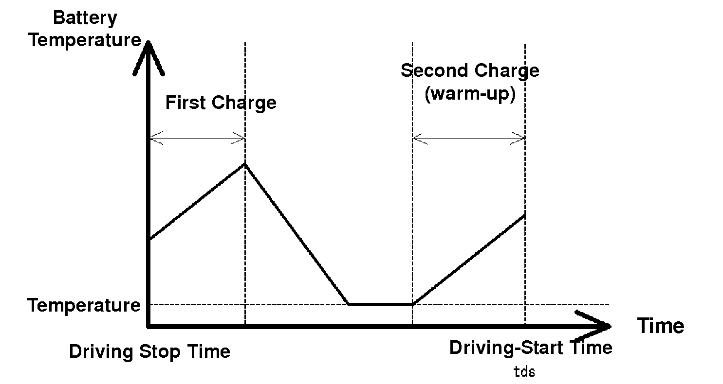
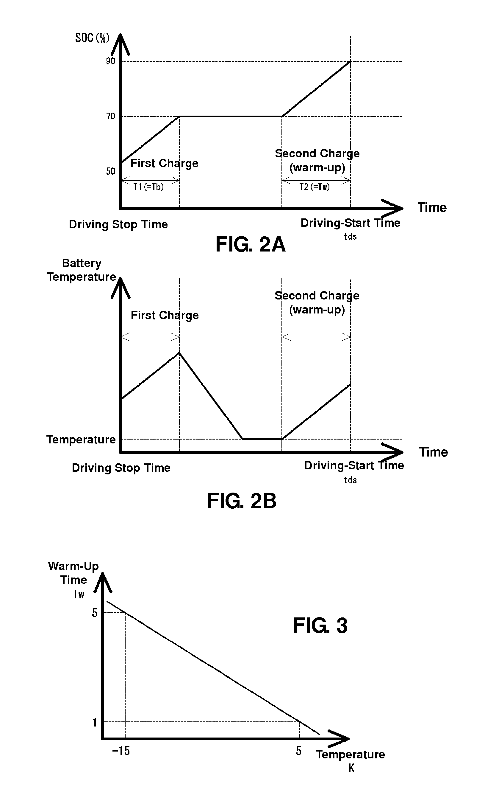
[0075]In the above-described first embodiment, the temperature of the battery 14 decreases during the period of time from the completion time of the first charge to the start time of the second charge as shown in FIG. 2B. In some case the battery's temperature may reduce to the outside temperature. Accordingly, there is a concern that in case the driving start is tried unexpectedly during this period, the temperature of the battery 14 is so cold that the prompt driving start may not be achieved.

Example

[0076]In a second embodiment, the battery charger 18 executes the first charge and the second charge, and additionally a third charge between the first and second charges as shown in FIG. 7 to cope with the above-described concern.

[0077]There may be some types of manners regarding the third charge. One of them shows the change of the SOC which is illustrated by a one-dotted broken line in FIG. 7. The third charge functions so as to be continuous to the second charge. Another one shows the change of the SOC which is illustrated by a two-dotted broken line in FIG. 7, in which the third charge starts continuously from the first charge and reaches to the SOC of Sc. Herein, Sc is the state of charge at the point where the second charge is started, and it is calculated by subtracting an increase due to only the charge with the warm-up time Tw from the maximum quantity. Further another one shows the change of the SOC which is illustrated by a broken line in FIG. 7, in which the third charg...


PUM


Abstract

The present invention is a charge method of a battery for an electric motor vehicle, in which a battery is charged by an outside electric source. A residual charge quantity of the battery is detected before charging. A maximum-quantity charge time Ttotal which is required for the residual charge quantity of the battery becoming the maximum quantity is calculated based on detection result. A driving-start time tds of the electric motor vehicle is estimated. A first charge is executed so as to be started from a driving stop of the electric motor vehicle, continued for a period of time which is shorter than the maximum-quantity charge time Ttotal, and completed before the driving-start time tds. A second charge is executed so as to be started after the first charge is completed and completed at the driving-start time tds.

Description

BACKGROUND OF THE INVENTION[0001]The present invention relates to a charge method of a battery for an electric motor vehicle and a charge device of a battery for an electric motor vehicle.[0002]In these days, electric motor vehicles which are driven by an electric motor receiving an electric power supplied from a battery have become noticeable. In these electric motor vehicles, it may be necessary that the battery is charged by an outside electric source when a residual charge quantity of the battery becomes small. However, the number of the electric motor vehicles spreading is still small, so there are not sufficiently many places where the outside electric source is located. Accordingly, there is a concern that the charging of the battery by the outside electric source could not be necessarily conducted properly when the residual charge quantity of the battery becomes small and the charging becomes necessary. Therefore, it should be necessary that the battery has been charged suff...

Claims


Application Information

Patent Timeline
IPC IPC(8): H02J7/00
CPCB60L11/1861Y02T10/7005Y02T10/7044Y02T90/14B60L11/1803B60L11/1816Y02T10/705Y02T10/7072B60L53/14B60L50/51B60L58/15Y02T10/70
Inventor WAKAYAMA, NORIHIRA
Owner MAZDA MOTOR CORP
Why Eureka
Try Eureka