
Touch screen tool

Active Publication Date: 2010-04-22
INHA UNIV RES & BUSINESS FOUNDATION
View PDF1 Cites 92 Cited by
  • Summary
  • Abstract
  • Description
  • Claims
  • Application Information

AI Technical Summary

Benefits of technology

[0011]Accordingly, the present invention is directed to a touch screen panel that substanti

Problems solved by technology

However, the resistive type touch screen has a problem of low light transmittance.
Also, since the two electrodes provided in the respective substrates have to be in contact by pressing the surface of the resistive type touch screen through the use of finger or pen, the resistive type touch screen has a problem of low endurance.
However, the capacitive type touch screen is high-priced.
In addition, the capacitive type touch screen does not work with a gloved finger or stylus pen.
However, the contaminated surface of IR type touch screen may cause a malfunction thereof.
Like the IR type touch screen, the contaminated surface of SAW type touch screen may cause a malfunction thereof.
In addition, the SAW type touch screen does not work with a gloved finger or stylus pen.

Method used


Image

  • Touch screen tool
  • Touch screen tool
  • Touch screen tool

Examples


Embodiment Construction

[0035]Reference will now be made in detail to the preferred embodiments of the present invention, examples of which are illustrated in the accompanying drawings. Wherever possible, the same reference numbers will be used throughout the drawings to refer to the same or like parts.

[0036]Hereinafter, a touch screen panel according to the present invention will be described with reference to the accompanying drawings.

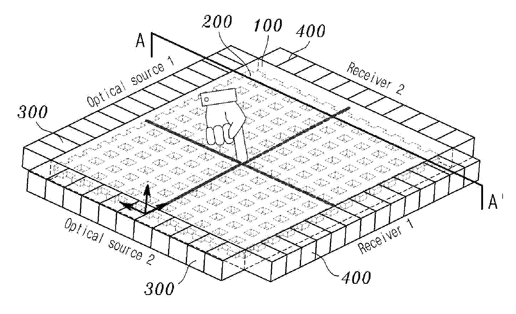
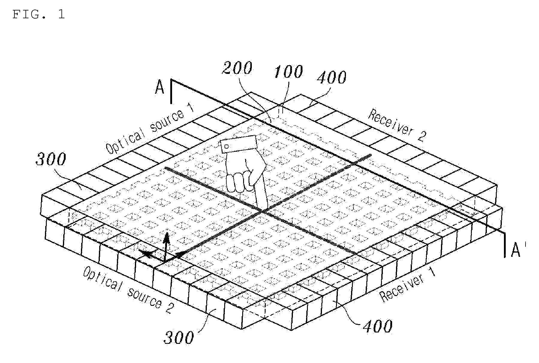
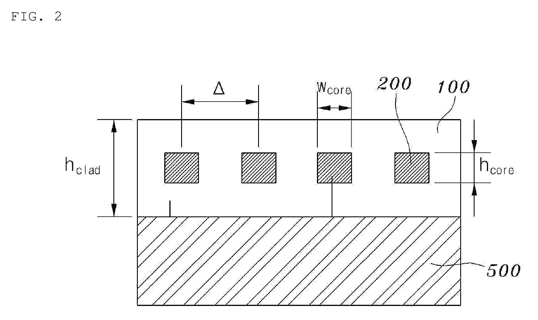
[0037]FIG. 1 is a perspective view illustrating a touch screen panel according to the present invention, and FIG. 2 is a cross section view along A-A′ of FIG. 1.

[0038]The touch screen panel according to the present invention basically uses an optical waveguide comprised of a core and a clad.

[0039]Referring to FIG. 1, the touch screen panel according to the present invention includes the clad 100, the core 200, an optical source 300, and a receiver 400.

[0040]First, the clad 100 is formed on an entire surface of a display panel 500, wherein the clad 100 is provided at a prede...


PUM


Abstract

A touch screen panel is disclosed, which is capable of sensing an exact position touched by a user or instrument, or a pressured applied to the touched position, wherein the touch screen panel comprises a core including a plurality of horizontal and vertical lines provided in a grid shape, wherein the core has a first refractive index, and an upper surface of the core is exposed to the atmosphere; an intermediate clad formed between each of gaps included in the core, wherein the intermediate clad has a second refractive index which is lower than the first refractive index, and a height of the intermediate clad is identical to a height of the core; an optical source configured to apply an optical signal to an input end of each of the plurality of horizontal and vertical lines; and a plurality of receivers configured to sense an intensity of the optical signal passing through an output end of each of the plurality of horizontal and vertical lines, the optical signal applied by the optical source.

Description

[0001]This application claims the benefit of the Korean Patent Application No. 10-2008-0101640, filed on Oct. 16, 2008, in the name of inventors Dae Seo PARK, Kwan Su CHOI, and Seung Gol LEE, titled “Touch Screen Panel”, which is hereby incorporated by reference as if fully set forth herein.BACKGROUND OF THE INVENTION[0002]1. Field of the Invention[0003]The present invention relates to a touch screen panel, and more particularly, to a touch screen panel which is capable of sensing an exact position touched by a user or instrument, or a pressured applied to the touched position.[0004]2. Discussion of the Related Art[0005]A touch screen can perform a predetermined function by detecting a letter or location on a display screen when it is touched by a user's hand or passive object.[0006]Generally, the touch screen is classified into a resistive type, a capacitive type, an infrared ray type (hereinafter, referred to as “IR type”), and a surface acoustic wave type (hereinafter, referred t...

Claims


Application Information

Patent Timeline
IPC IPC(8): G06F3/041
CPCG06F3/0421G06F3/0412G06F3/0416G06F2203/04103
Inventor PARK, DAE SEOCHOI, KWAN SULEE, SEUNG GOL
Owner INHA UNIV RES & BUSINESS FOUNDATION
Learn More