
Methods and apparatuses for data collection and communication in drill string components

a technology of data collection and communication, applied in the field of transmission of data within a wellbore, can solve the problems of high signal attenuation, slow data transmission rate of mud telemetry, and inability to collect or retrieve large amounts of desired data

Active Publication Date: 2010-04-22
BAKER HUGHES INC
View PDF29 Cites 68 Cited by
  • Summary
  • Abstract
  • Description
  • Claims
  • Application Information

AI Technical Summary

Benefits of technology

[0029]FIG. 11 is a block diagram of a drillstring communication network according to one or more embodiments of the present invention;
[0030]FIG. 12 is

Problems solved by technology

However, much of the desired data is not easily collected or retrieved.
However, problems still remain with the transmission of subsurface data from subsurface sensors to surface monitoring equipment, while drilling operations continue.
As examples, mud telemetry has a slow data transmission rate, high signal attenuation, difficulty in detecting signals over mud pump noise, maintenance requirements, and the inconvenience of interfacing and matching the data telemetry system with the choice of mud pump, and drill bit.
Electrical telemetry using electrical conductors in the transmission of subsurface data also presents an array of unique problems.
One significant difficulty is making a reliable electrical connection at each pipe junction.
Unfortunately, such conventional subs are expensive and are configured as dedicated downhole components that must be placed in the drillstring instead of, or in addition to, a simple drill pipe or drill collar.

Method used


Image

  • Methods and apparatuses for data collection and communication in drill string components
  • Methods and apparatuses for data collection and communication in drill string components
  • Methods and apparatuses for data collection and communication in drill string components

Examples


Embodiment Construction

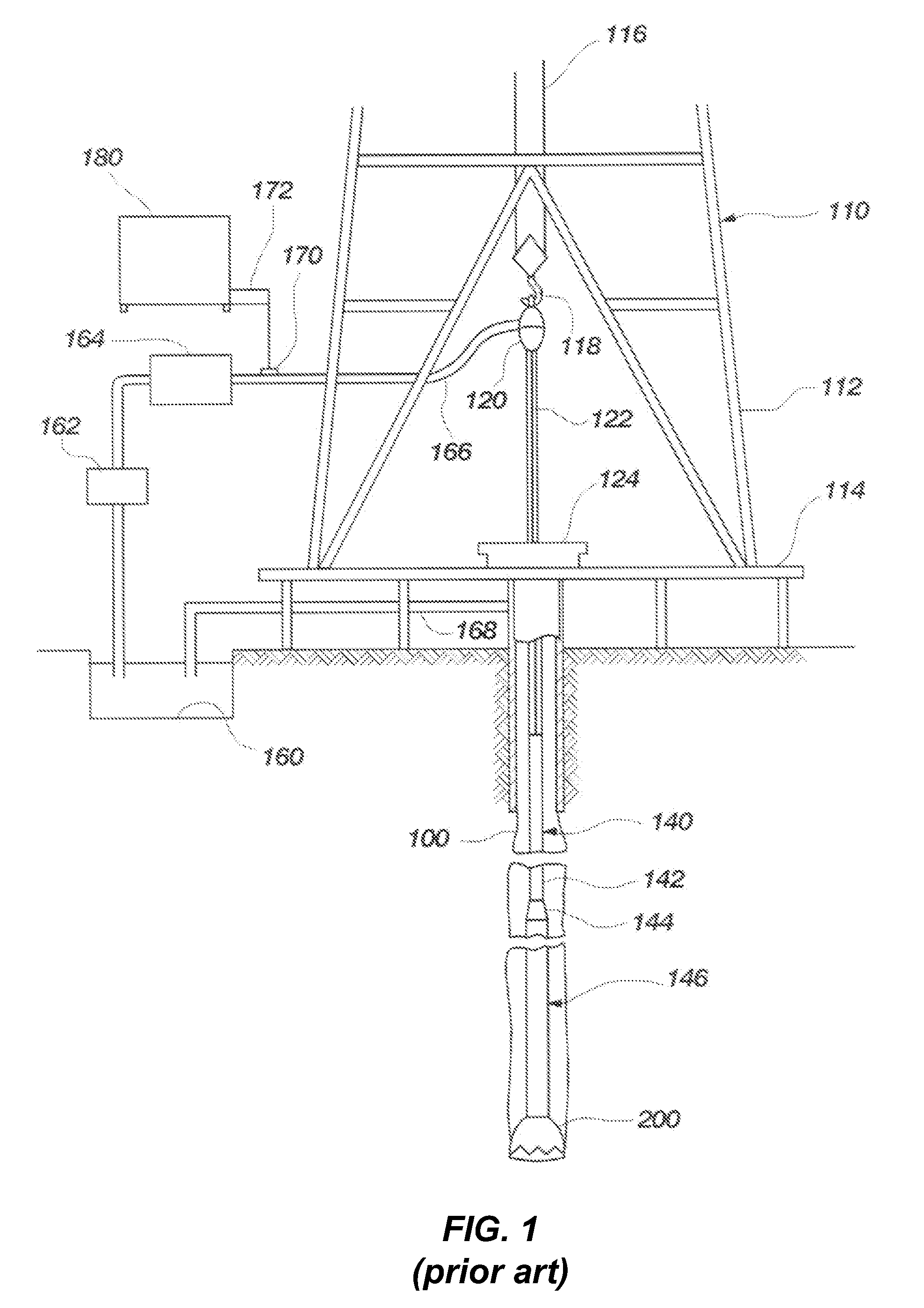
[0032]FIG. 1 depicts an example of a conventional apparatus for performing subterranean drilling operations. Drilling rig 110 includes a derrick 112, a derrick floor 114, a draw works 116, a hook 118, a swivel 120, a Kelly joint 122, and a rotary table 124. A drillstring 140, which includes a drill pipe section 142 and a drill collar section 144, extends downward from the drilling rig 110 into a borehole 100. The drill pipe section 142 may include a number of tubular drill pipe members or strands connected together and the drill collar section 144 may likewise include a plurality of drill collars. In addition, the drillstring 140 may include a measurement-while-drilling (MWD) logging subassembly and cooperating mud pulse telemetry data transmission subassembly, which are collectively referred to as an MWD communication system 146, as well as other communication systems known to those of ordinary skill in the art.

[0033]During drilling operations, drilling fluid is circulated from a m...


PUM


Abstract

A drill string component includes a box-end and a pin-end. Each end includes a signal transceiver, which are operably coupled together. Each signal transceiver communicates with another signal transceiver in another component to form a communication network in the drillstring. An end-cap may be placed in the central bore of the pin-end of a component to form an annular chamber between a side of the end-cap and a wall of the central bore of the pin-end when the end-cap is disposed in the central bore. In some embodiments, an electronics module may be placed in the annular chamber and configured to communicate with one of the signal transceivers. Accelerometer data, as well as other sensor data, at various locations along the drillstring may be sampled by the electronics module and communicated to a remote computer. Drillstring motion dynamics, such as vibration, may be determined based on the accelerometer data.

Description

FIELD OF THE INVENTION[0001]The present invention relates generally to transmission of data within a wellbore and more particularly to methods and apparatuses for obtaining downhole data or measurements while drilling.BACKGROUND OF THE INVENTION[0002]In rotary drilling, a rock bit is threaded onto a lower end of a drillstring. The drillstring is lowered and rotated, causing the bit to disintegrate geological formations. The bit cuts a borehole somewhat larger than the drillstring, so an annulus is created between the walls of the borehole and the drill string. Section after section of drill pipe, or other drillstring tool, is added to the drillstring as new depths are reached.[0003]During drilling, a fluid, often called “mud,” is pumped downward through the drill pipe, through the drill bit, and up to the surface through the annulus, carrying cuttings from the borehole bottom to the surface.[0004]It is often useful to detect borehole conditions, drill bit conditions, and drillstring...

Claims


Application Information

Patent Timeline
IPC IPC(8): E21B47/16
CPCE21B17/028E21B17/042E21B47/12E21B47/02E21B47/01
Inventor SULLIVAN, ERIC C.PASTUSEK, PAUL E.
Owner BAKER HUGHES INC
Learn More