Eureka AIR delivers breakthrough ideas for toughest innovation challenges, trusted by R&D personnel around the world.

Self Leveling Dynamically Stable Radial Bearing

Active Publication Date: 2010-04-22
BAKER HUGHES INC
View PDF27 Cites 9 Cited by
  • Summary
  • Abstract
  • Description
  • Claims
  • Application Information

AI Technical Summary

Benefits of technology

[0021]The invention has several advantages. The reliability of submersible pumping motor units may be greatly increased by the use of dynamic stability bearings. By replacing the plain sleeve bearings within the motor with dynamically stable bearings such as multi-pad bearings, vibration is reduced. The floating segmented pads can self align, preventing half speed oil whirl and dampening excessive side loading.

Problems solved by technology

The absence of a substantial load results in an unstable or marginally stable bearing operation that can result in metal-to-metal contact in the bearings, which accelerates bearing failure.

Method used


Image

  • Self Leveling Dynamically Stable Radial Bearing
  • Self Leveling Dynamically Stable Radial Bearing
  • Self Leveling Dynamically Stable Radial Bearing

Examples


Embodiment Construction

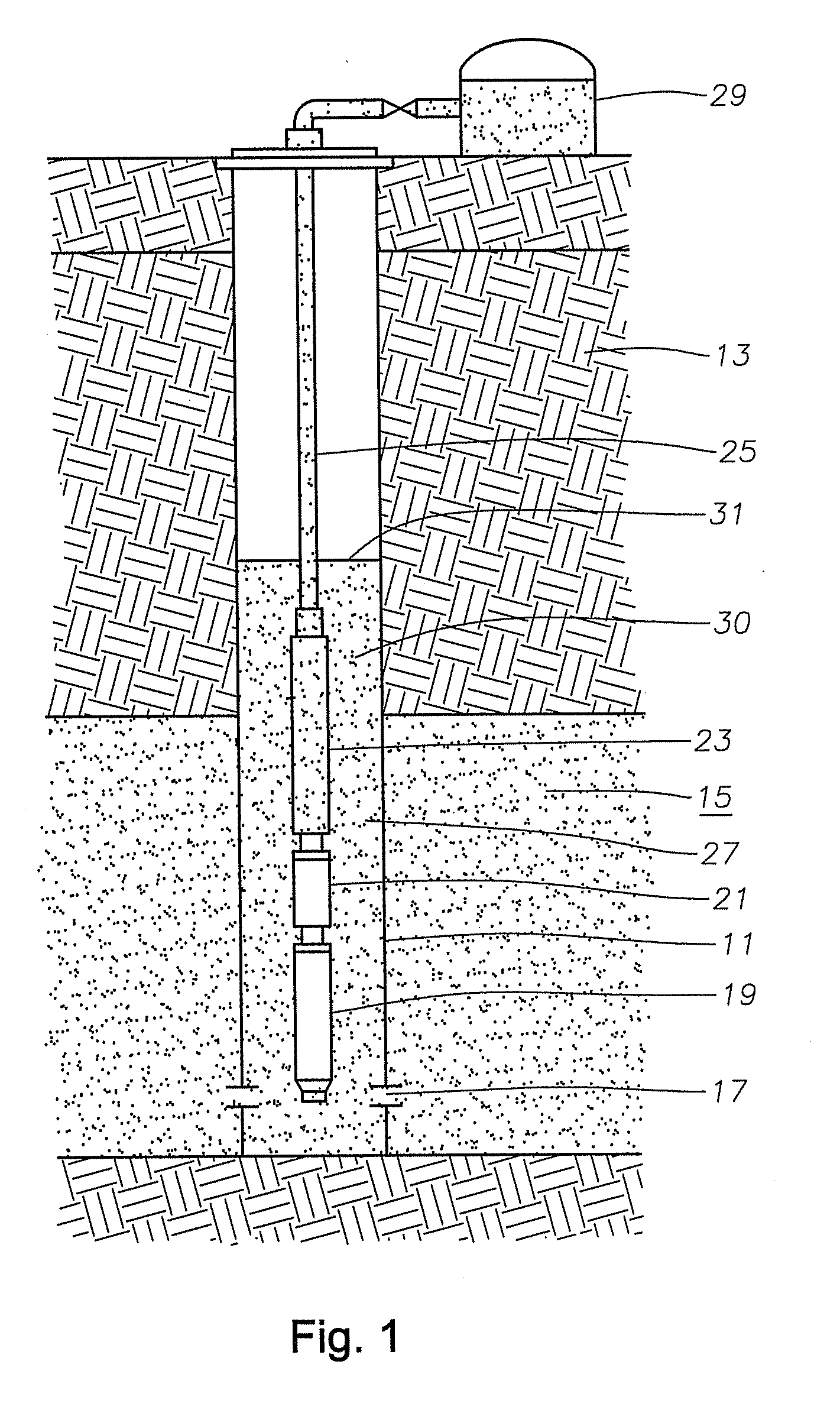
[0012]Referring now to FIG. 1, a well casing 11 is located within a well in an earth formation 13 and also passes through a producing zone 15. Perforations 17 formed in the well casing enable the fluid in the producing zone 15 to enter the casing 11.

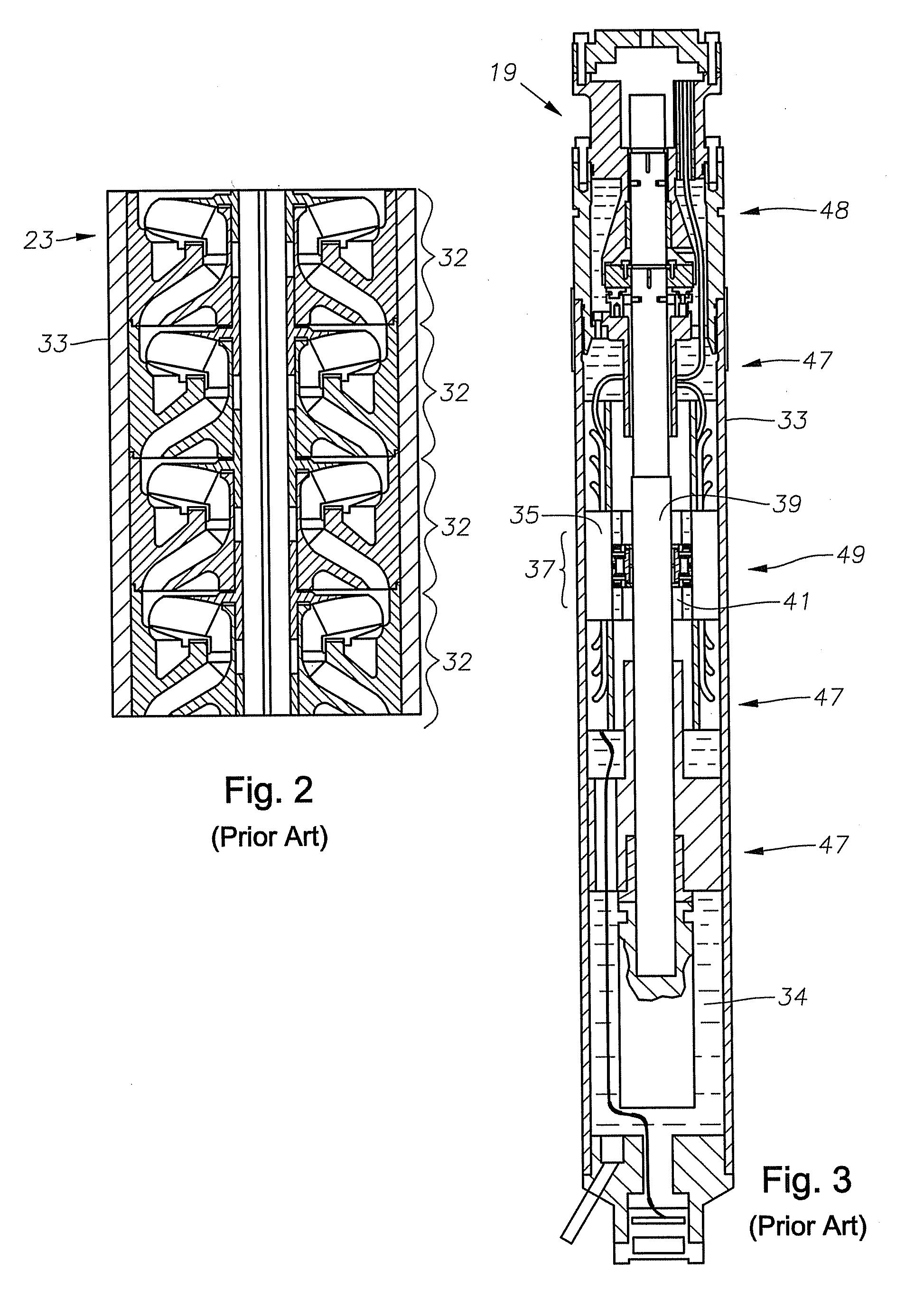
[0013]The submersible pump assembly includes an electrical motor 19 that is located in the well. The shaft of motor 19 extends through a seal section 21 and is connected to a centrifugal pump 23. Pump 23 is connected to tubing 25 for conveying well fluid 27 to a storage tank 29 at the surface. The casing 11 will contain an operating fluid level 31 of well bore fluid 30 in the annulus of casing 11. The pump 23 must be capable of delivering fluid 30 for the distance from level 31 to the surface tank 29. Preferably, pump 23 is a centrifugal pump comprised of a plurality of pump stages 32 (FIG. 2) within a housing 33.

[0014]Referring now to FIGS. 3 and 4, a prior art submersible pump motor 19 is shown. Submersible pump motor 19 has a housing ...


PUM


Abstract

A bearing configuration for use in electrical submersible pumps having improved stability. The bearing configuration comprised of a plurality of pads, each able to freely tilt and adjust to the surface of the shaft.

Description

FIELD OF THE INVENTION [0001]This invention relates in general to submersible pump motors, and in particular to the incorporation of bearings that provide increased stability.BACKGROUND OF THE INVENTION [0002]A submersible pump is a centrifugal pump having a submersible motor that rotates a shaft to drive a pump. The submersible pump is for producing high volumes of oil and water. A typical submersible pump motor may be from 6-60 feet in length and be rated at several hundred horsepower. Each motor has a stator secured within a tubular housing. A rotor secured to the shaft rotates within a stator.[0003]Because of the long length of the motor, the rotor is made up of a number of rotor sections. Each rotor section comprises a large number of flat disks called laminations that are secured by copper rods. The rotor sections are spaced apart from each other. A bearing assembly is located between each section for maintaining the shaft in axial alignment. The rotor sections are keyed to th...

Claims


Application Information

Patent Timeline
IPC IPC(8): F04D13/10F04D29/046F04D29/06
CPCF04D13/10F04D29/047F16C17/03
Inventor PARMETER, LARRY J.CRAIG, CHAD A.
Owner BAKER HUGHES INC
Why Eureka
Eureka Blog
Learn More