Eureka AIR delivers breakthrough ideas for toughest innovation challenges, trusted by R&D personnel around the world.

Nuclear power plant having a protective superstructure

Active Publication Date: 2021-12-07
ROLLS-ROYCE SMR LTD
View PDF14 Cites 0 Cited by
  • Summary
  • Abstract
  • Description
  • Claims
  • Application Information

AI Technical Summary

Benefits of technology

The patent describes a design for a superstructure that helps reduce pressure differences between two ends in case of flooding. This design has an oval-shaped profile and helps water flow around it.

Problems solved by technology

Whilst attempts are typically made to prevent flooding of nuclear power plants by installation of coastal defences such as seawalls, if an extreme enough event occurs these may be quickly overwhelmed and the plant left vulnerable.

Method used


Image

  • Nuclear power plant having a protective superstructure
  • Nuclear power plant having a protective superstructure
  • Nuclear power plant having a protective superstructure

Examples


Embodiment Construction

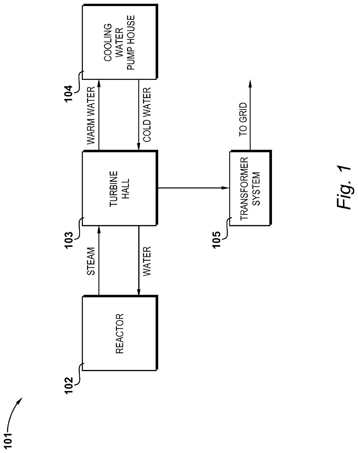
[0014]A block diagram of the primary functions of a nuclear power plant is shown in FIG. 1. The nuclear power plant, indicated generally at 101, is in the present example a small modular reactor (SMR). SMRs are smaller than conventional nuclear power plants, and assembled from component parts manufactured offsite.

[0015]As is typical with nuclear power plants, the nuclear power plant 101 is split into several different sections termed islands. The nuclear reactor 102 itself is located in an appropriate containment structure on a reactor island, a turbine 102 is located in a hall on a turbine island, and a cooling water pump house 104 is located on a cooling island. In practice, the nuclear power plant 101 operates in the conventional manner, in that heat from nuclear fission in the reactor 102 raises steam, which is expanded through the turbine in accordance with the Rankine cycle. The steam condenses and is then returned as water to the reactor. In conjunction with this, heat is rem...


PUM


Abstract

A nuclear power plant having a protective superstructure including a first end region configured to cover a nuclear reactor in a containment structure, a second end region opposite the first end region and configured to cover a cooling water pump house, and a central region between the first and second end regions and configured to cover a turbine hall. The superstructure has an oval-shaped plan profile, the oval having a greater degree of curvature at the first end region than at the second end region.

Description

CROSS-REFERENCE TO RELATED APPLICATIONS[0001]This specification is based upon and claims the benefit of priority from United Kingdom patent application number GB 1708234.8 filed on May 23, 2017 and the entire contents of which are incorporated herein by reference.BACKGROUNDField of the Disclosure[0002]This disclosure relates to nuclear power plant having a protective superstructure.Description of the Related Art[0003]Nuclear power plants are typically built near to large bodies of water to supply their need for coolant. Whilst some are situated adjacent to rivers, most are sited in coastal locations. In doing so, there is a need to mitigate flood of the plant due to excessive wave overtopping, extreme tides, storm surges, or even seismically-initiated tsunami.[0004]Whilst attempts are typically made to prevent flooding of nuclear power plants by installation of coastal defences such as seawalls, if an extreme enough event occurs these may be quickly overwhelmed and the plant left vu...

Claims


Application Information

Patent Timeline
IPC IPC(8): E04H5/02E04H9/14G21C13/093G21D1/04E04B1/32
CPCE04H5/02E04H9/145G21C13/093G21D1/04E04B1/32G21D5/00G21C13/02G21D1/02Y02A50/00Y02E30/30Y02E30/00E04H9/04G21C13/00G21D1/00
Inventor MARQUEZ-SANTOYO, JOSE ARICHARDSON, MARK JEDWARDS, GARETHSMITH, PAUL C
Owner ROLLS-ROYCE SMR LTD
Why Eureka
Eureka Blog
Learn More