Eureka AIR delivers breakthrough ideas for toughest innovation challenges, trusted by R&D personnel around the world.

High efficiency dual shell stirling engine

Inactive Publication Date: 2000-03-28
ADI THERMAL POWER
View PDF25 Cites 12 Cited by
  • Summary
  • Abstract
  • Description
  • Claims
  • Application Information

AI Technical Summary

Benefits of technology

The Stirling engine described in this patent is unique in its use of an insulating dual shell containment system. The outer shell provides a time varying pressure field which significantly reduces the pressure differential on the critical high temperature components allowing th

Problems solved by technology

Cost reduction has also been a key research area for these engines due to their increased complexity over open cycle engines such as the Internal Combustion and Brayton engines which have achieved extensive commercialisation success.
The combination of high pressures and temperatures has limited Stirling engine temperatures to around 800 Centigrade.
Ceramic materials have been investigated, as a technique to allow higher temperatures, however the brittleness and high cost have made them difficult to implement.
The performance of the Stirling engine is thusly limited by the use of mesh screens.
The slot reduces the pressure drop but is limited by the amount of surface area in a single slot regenerator.
With this technique a significant amount of pumping and valving hardware is required to move the working fluid.
This is complicated by the high working pressures which increases the size of the pumping hardware.
This technique increases the total system volume which lowers the power but also results in a significant reduction in efficiency due the larger dead volume which the engine is exposed to for the entire piston stroke.
Reducing the plate angle results in reduced movement of the piston resulting in reduced power levels.
The throttling technique, using the plate angle, has the disadvantage of a higher system weight due to the large loads generated when converting the wobble motion of the plate to torque.
A further feature, which has been a significant problem for Stirling engines, is the sealing system.
Working fluid leakage, at the seals, is a large problem for external shaft systems.
The disadvantages to the high pressure seal include the high cost and potential requirement to replace working fluid in the engine.
The high pressure seals have limited lifetimes which requires replacement of the seal.

Method used


Image

  • High efficiency dual shell stirling engine
  • High efficiency dual shell stirling engine
  • High efficiency dual shell stirling engine

Examples


main embodiment

OPERATION--MAIN EMBODIMENT

Working Fluid Movement

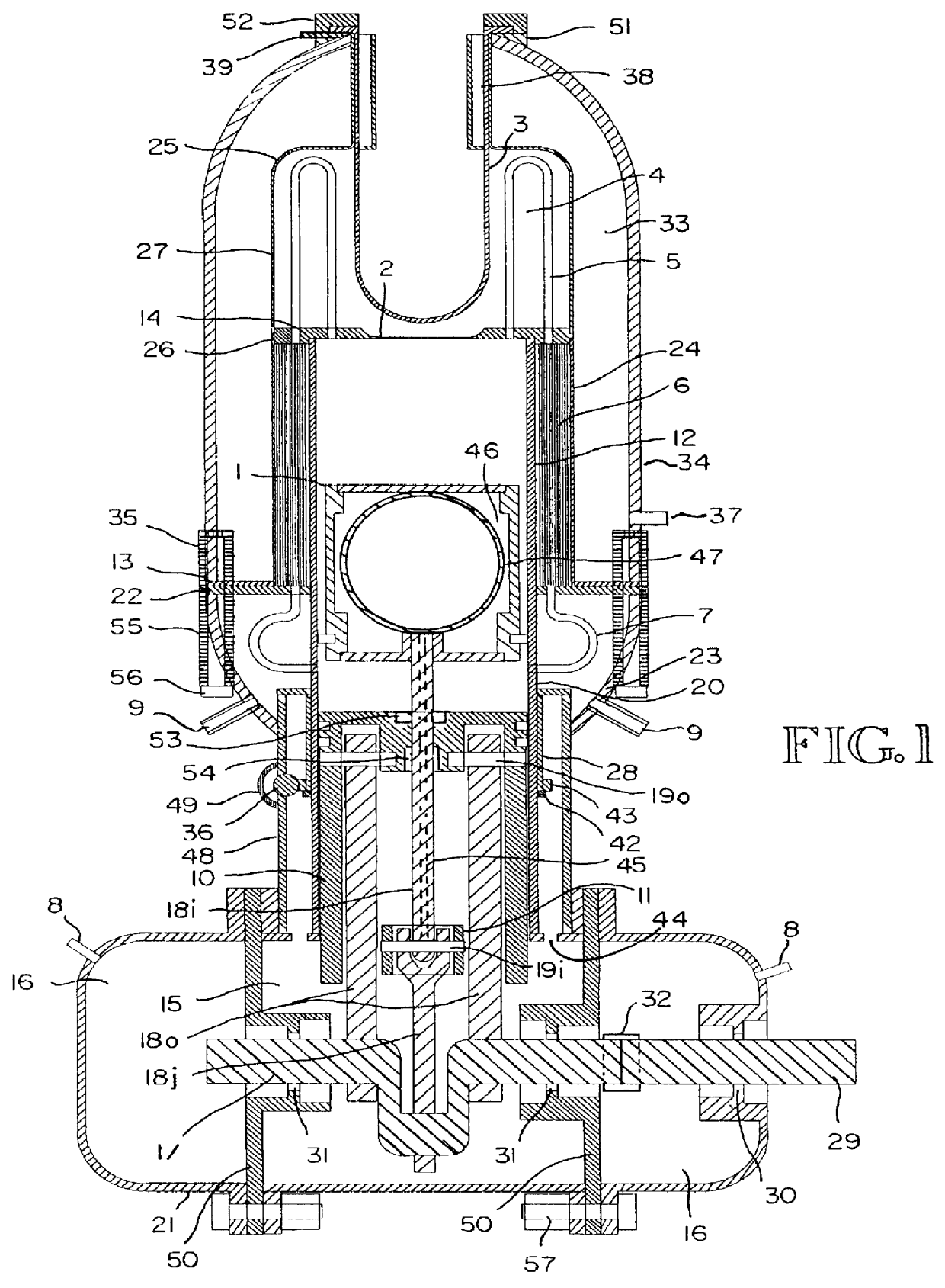
The operation of the Stirling engine, in FIG. 1, is described below. The Stirling engine can be run to produce either power out or as a heat pump providing cooling. The difference is determined by whether the displacer phase angle is ahead of or behind the power piston. FIG. 1 shows an engine designed to produce rotary shaft power. The cylinder(20) is attached to the lower housing(21) and contains both the power piston(10) and the displacer piston(1). To produce shaft power the displacer piston(1) is attached, through the set of connecting rods(18i and 18j), to the crankshaft(17) at an angle which is 60 to 120 degrees ahead of the set of outer connecting rods(18o) and power piston(10). The lower piston, the power piston(10), provides the power to the crankshaft(17).

The upper piston, the displacer piston(1), is driven by the crankshaft(17) and provides the means to move the working fluid between the chamber directly below the displacer ...


PUM


Abstract

A stirling engine which uses a dual pressure shell surrounding the high pressure and temperature engine components. Space between the shells is filled with an incompressible and insulating liquid material, such as a liquid salt. The liquid may have a filler material to prevent excessive movement. The liquid provides a time varying pressure field, driven by the pressure variations in the Stirling engine working fluid, which cancels the pressure differential on heat transfer tubing. The heat transfer tubing is inside of a dome which contains an incompressible, highly thermally conductive liquid, such as Sodium. The combination described allows a Stirling engine to operate at significantly higher temperatures and pressures relative to existing technology.

Description

1. Field of the InventionThis invention relates to Stirling Engines, specifically to:1. Improvements in maximum operating temperatures.2. Improvements in the regenerator to maximize performance.3. Improvements in a throttling system designed for low cost and maximum performance4. Improvements in high pressure shaft sealing to allow external drives.2. Prior ArtA patent search was made investigating the types of improvements in Stirling Engines which have been accepted for United States Patents over the last 10 years. The author has researched the technologies over the last 50 years to understand the development of the state of the art for Stirling engines used as power systems.Stirling engine performance improvements are continually being sought to increase the benefit of these energy conversion devices and allow large scale commercial introduction into the marketplace. Cost reduction has also been a key research area for these engines due to their increased complexity over open cycl...

Claims


Application Information

Patent Timeline
IPC IPC(8): F02G1/00F02G1/043
CPCF02G1/043F02G2243/02F02G2243/04Y10S165/342
Inventor BLIESNER, WAYNE THOMAS
Owner ADI THERMAL POWER
Why Eureka
Eureka Blog
Learn More