Eureka AIR delivers breakthrough ideas for toughest innovation challenges, trusted by R&D personnel around the world.

Thermal control system for turbines

Inactive Publication Date: 2010-10-14
ROLLS ROYCE PLC
View PDF8 Cites 7 Cited by
  • Summary
  • Abstract
  • Description
  • Claims
  • Application Information

AI Technical Summary

Benefits of technology

[0008]The thermal control system according to the present invention has a simple configuration, therefore reducing the risk of malfunction, as well as cost. Cooling air may be provided directly onto the casing or, if present, each thermal control ring from a high pressure source such as a fan or compressor associated with the turbine, and evacuated or leaked through a circumferential gap. If the turbine forms part of a gas turbine engine, the high pressure source may be the fan or compressor which also forms part of the gas turbine engine, and which is in flow communication with the turbine. The pressure differential between the inside and the outside of the circumferential flow chamber may be very low, reducing the leakage and thereby improving efficiency of cooling. Due to the low pressure differential, the wall of a circumferential flow chamber may be moulded of a thin, light material, such as metal foil, and the wall may be made of overlapping sections of material. Furthermore, the system is flexible, and may be readily applied to turbines of differing sizes and power, which have differing operational cooling requirements.
[0009]Embodiments of the invention can provide an efficient system for controlling the blade clearance of turbine machinery, which is simple and reliable, cheap and wherein the amount of air bled from the high-pressure portion of the turbine machinery can be tightly controlled.
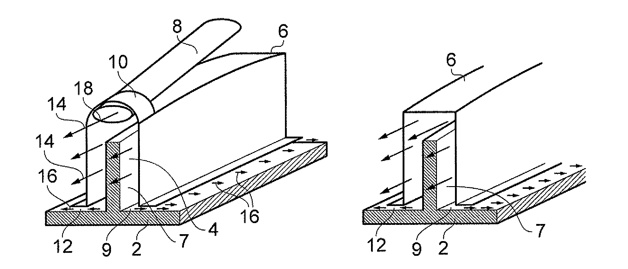
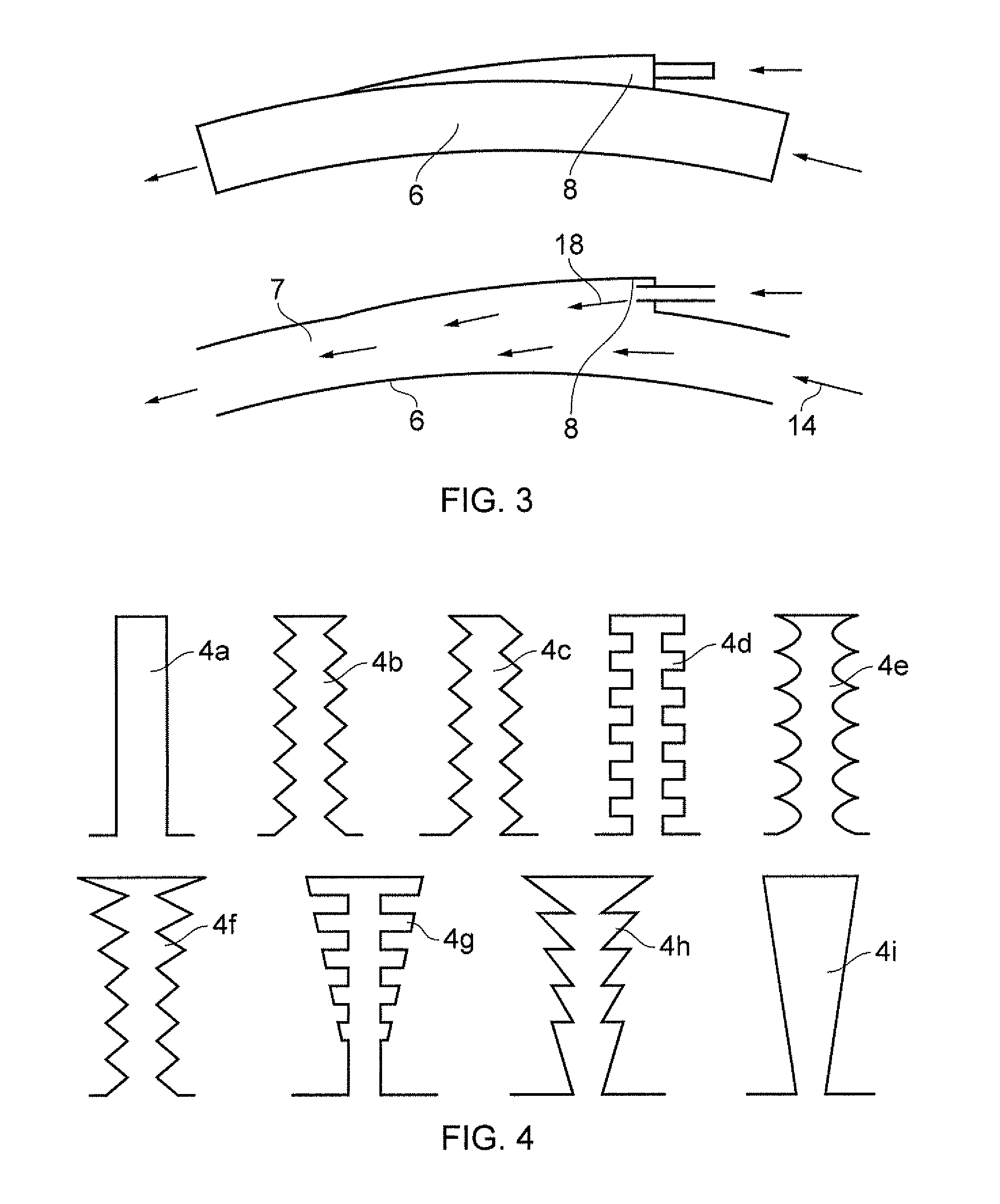
[0015]The thermal control rings of the thermal control system according to the invention may have various shapes. For example, the cross-section of the thermal control rings may be rectangular, triangular, angled, dented, forked, or of any other shape. Different shapes of thermal control rings may be used to improve the thermal exchange between a thermal control rings and the thermal fluid, as well as to influence the flow of the thermal fluid within the space between the circumferential chamber and the thermal ring.
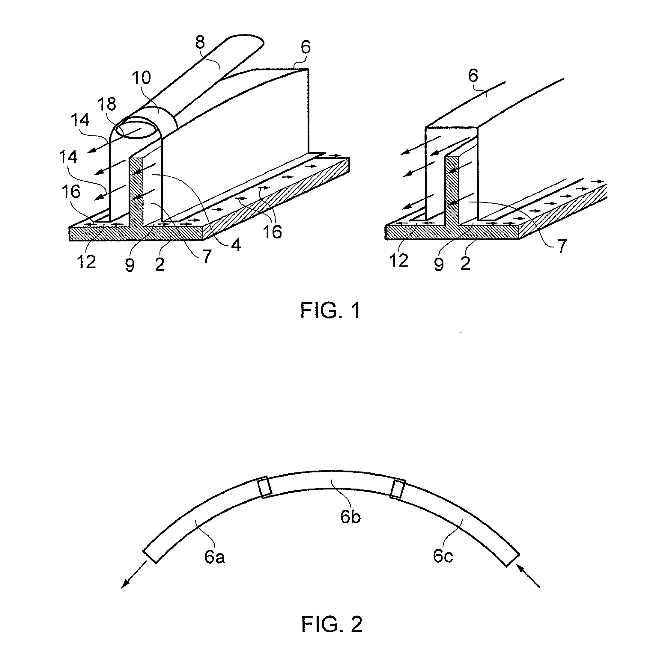
[0016]In embodiments of the invention, a circumferential flow chamber may narrow in cross-section, in the direction of the flow of the thermal fluid, from a position where a connection to a duct is provided. This can help to ensure even flow of the thermal fluid throughout a circumferential chamber. At the injection point, the area of the cross-section of the circumferential chamber would be in proportion to the sum of the entrained fluid flow and the injected fluid flow. The area may then linearly reduce in the flow direction, such that it is in proportion to the entrained flow just before the next injection point. With this setup, the pressure differential within different sections of the circumferential chamber may be reduced to a minimum, which ensures even flow throughout the circumferential chamber.
[0017]The thermal fluid, which is injected into the circumferential chambers of the thermal control system according to the invention may be preferably air provided from a high pressure section of the turbine machinery, such as a fan or compressor associated with the turbine. The thermal ducts of the thermal control system may lead from the high pressure part of the turbine to the injection points of the circumferential chambers. This can help ensure that the temperature control of the turbine casing is in line with the internal temperature of the turbine.
[0018]A circumferential chamber wall of the thermal control system for a turbine casing according to the present invention may be made of an insulating material. This material may be a light malleable metal sheet, which can be easily moulded into the required form. It may also consist of two layers of metal sheets comprising a gap between them, to improve insulation. It is advantageous if a circumferential chamber wall has good insulating properties, in order to ensure that thermal exchange occurs predominantly between the thermal fluid and the thermal control ring(s), and that as little heat as possible is exchanged between the thermal fluid and the inside of the turbine.

Problems solved by technology

One factor reducing the efficiency of gas turbines is the thermal expansion and contraction of different turbine machinery parts associated with alterations of power.
A particular issue concerns the clearances between the tips of the turbine blades and a casing which is mounted radially outwardly of and circumferentially surrounds the blade tips.
For example, at the exhaust end of the gas turbine, the turbine machinery has the problem of matching the casing diameter to the tip diameter of the blades.
This leads to excessive tip / casing clearances, lowering the efficiency of the turbine, and therefore to higher fuel consumption.
Since a certain amount of cooling air is bled from the high pressure section of the turbine, a reduction of thrust or efficiency occurs.
Additionally, the cooling needs to be adjusted such that no circumferential cooling gaps occur, which would lead to a distortion of the casing shape, and therefore increased wear and tear, caused by temperature differences.
A further drawback results from leakages in the cooling air suppliers, which reduce the efficiency of the cooling and increase the amount of cooling air which needs to be bled from the turbine machinery, therefore reducing thrust or efficiency.
Overall, the system is expensive, complicated and heavy and is prone to mechanical malfunction.

Method used


Image

  • Thermal control system for turbines
  • Thermal control system for turbines
  • Thermal control system for turbines

Examples


Embodiment Construction

[0036]As illustrated in FIG. 1, thermal fluid, typically air, flows, in a direction circumferential of a turbine machinery casing 2 which is mounted radially outwardly of and circumferentially surrounding turbine blade tips of turbine blades of a turbine (not shown), through a circumferential flow chamber 7 between a thermal control ring 4, typically a dummy flange on the casing 2 as indicated in FIG. 1, and a circumferential chamber wall 6. A dummy flange is a flange which plays no part in mounting the casing in the engine or other equipment of the turbine assembly. The thermal control ring 4 is mounted on a radially outward surface of the turbine casing 2 and the flow chamber 7 is located radially outwardly of that surface. Hence there is a region of the casing 2 which is bounded by the circumferential flow chamber 7. The circumferential chamber walls 6 define an opening 9 on the radially inward side of the chamber 7 adjacent the surface of the turbine casing 2. The embodiment sho...


PUM


Abstract

A thermal control system for a turbine casing (2) mounted radially outwardly of and circumferentially surrounding blade tips of the turbine blades, the system comprising: one or more circumferential chamber walls (6), each disposed around the casing (2), each to form a circumferential flow chamber (7) radially outward of said surface of the turbine casing (2), each to form a circumferential gap (12) between the circumferential chamber wall (6) concerned and said surface of the turbine casing (2), and the one or more circumferential chamber walls (6) define at least one opening (9) on the radially inward side of the chamber (7) adjacent the surface of the turbine casing (2) such that a thermal fluid injected into the flow chamber (7) concerned may leak out through the circumferential gap (12) via the opening (9), and means to induce circumferential flow on the surface of the casing (2) bounded by the circumferential flow chamber (7) comprising one or more ducts (8) radially outwardly connected to the or each circumferential flow chamber (7), via which the thermal fluid can be injected into the flow chamber or chambers (7) concerned in a circumferential direction.

Description

FIELD OF THE INVENTION[0001]The invention concerns a thermal control system for turbines.BACKGROUND OF THE INVENTION[0002]Efficiency of operation is of paramount importance in gas turbines, in particular aero gas turbines.[0003]One factor reducing the efficiency of gas turbines is the thermal expansion and contraction of different turbine machinery parts associated with alterations of power. A particular issue concerns the clearances between the tips of the turbine blades and a casing which is mounted radially outwardly of and circumferentially surrounds the blade tips. For example, at the exhaust end of the gas turbine, the turbine machinery has the problem of matching the casing diameter to the tip diameter of the blades. When the turbine machinery power is altered, the casing changes diameter relatively quickly in response to the turbine gas temperature change, but a disk supporting the blades reacts more slowly. This leads to excessive tip / casing clearances, lowering the efficie...

Claims


Application Information

Patent Timeline
IPC IPC(8): F02C7/12
CPCF01D11/24F05D2260/20F02C7/12F01D25/14F05D2260/22141
Inventor KIRBY, STUART J.
Owner ROLLS ROYCE PLC
Why Eureka
Eureka Blog
Learn More