Spinal buttress plate

Active Publication Date: 2010-04-22
K2M
View PDF39 Cites 53 Cited by
  • Summary
  • Abstract
  • Description
  • Claims
  • Application Information

AI Technical Summary

Benefits of technology

[0012]The teeth are disposed in spaced-apart relation on the bottom surface of the body and are positionable within the one or more vertebrae. The teeth and the ledge are disposed on opposing ends of the body. One or both of the teeth are mounted to the body by a footing.
[0013]In one aspect, a method of attaching a buttress plate includes providing a buttress plate including a body having an annular lip defining an opening, a ledge defining an aperture, and a pair of teeth. The method includes providing an instrument having a rod and a prop extending therefrom adapt

Problems solved by technology

Vertebrae, like any other bone, often fracture and require surgical reconstruction.
If the grafting material does not maintain its position at the site of application, several potential problems may occur.
First and foremost, the material no longer functions for its intended purpose.
As a result, complications may arise such as joint incongruity, arthritis, stiffness, pain, crepitance with joint motion, non-union or malunion.
In addition to losing intended function, migration of graft material may have additional deleterious effects.
Migration of grafting material into adjacent soft tissues may initiate an inflammatory reaction or caus

Method used


Image

  • Spinal buttress plate
  • Spinal buttress plate
  • Spinal buttress plate

Examples


Embodiment Construction

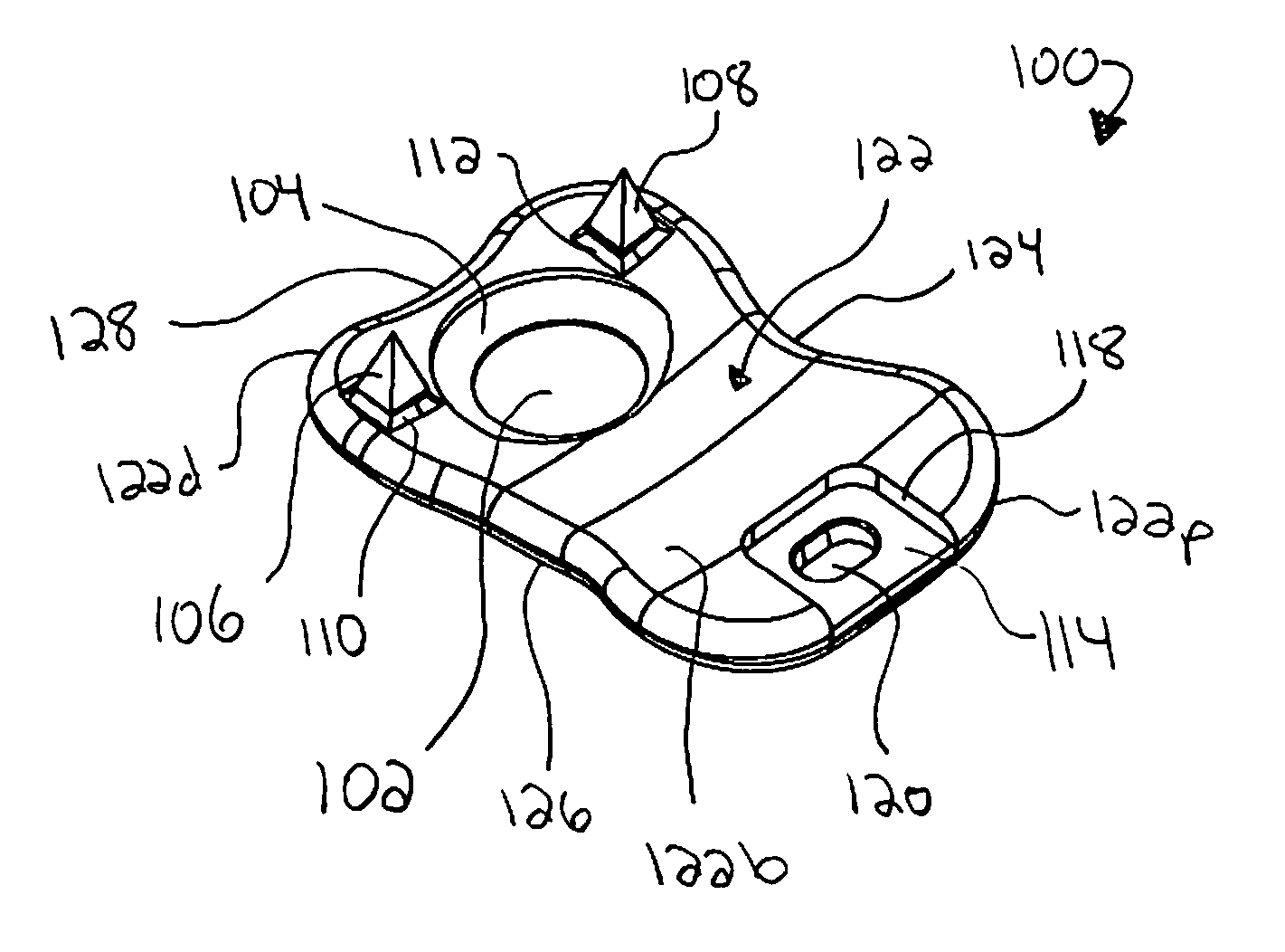
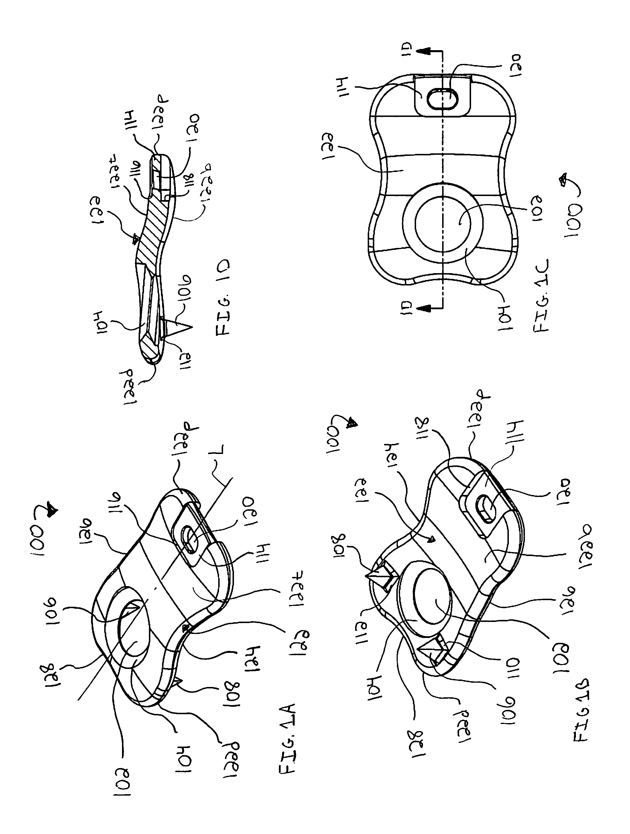
[0026]Various embodiments of the presently disclosed spinal buttress plate and system will now be described in detail with reference to the drawings, wherein like reference numerals identify similar or identical elements. In the drawings and in the description that follows, the term “proximal,” will refer to the end of a device or system that is closest to the operator, while the term “distal” will refer to the end of the device or system that is farthest from the operator. In addition, the term “cephalad” is used in this application to indicate a direction toward a patient's head, whereas the term “caudad” indicates a direction toward the patient's feet. Further still, for the purposes of this application, the term “medial” indicates a direction toward the middle of the body of the patient, whilst the term “lateral” indicates a direction toward a side of the body of the patient (i.e., away from the middle of the body of the patient). The term “posterior” indicates a direction towar...


PUM


Abstract

A spinal buttress plate includes a body having a top surface and a bottom surface and including an annular lip, a ledge, and a pair of teeth. The annular lip defines an opening. The annular lip and the opening are adapted to engage a screw for facilitating the securement of the buttress plate to one or more vertebrae. The ledge defines an aperture. The ledge and aperture are adapted to engage an instrument for positioning the buttress plate adjacent a spinal bone graft. The teeth are disposed in spaced-apart relation on the bottom surface of the body and are positionable within the one or more vertebrae.

Description

CROSS REFERENCE TO RELATED APPLICATIONS[0001]This application claims priority to, and the benefit of, U.S. Provisional Patent Application Ser. No. 61 / 107,115, filed Oct. 21, 2008, the contents of which are hereby incorporated by reference in their entirety.BACKGROUND[0002]1. Technical Field[0003]The present disclosure relates generally to a spinal plate and, more particularly, to a spinal buttress plate for providing spinal bone graft support.[0004]2. Background of Related Art[0005]The human spinal column is a highly complex structure. It includes more than twenty discrete bones, known as vertebrae, coupled sequentially to one another to house and protect critical elements of the nervous system. Vertebrae, like any other bone, often fracture and require surgical reconstruction. Grafting materials such as autologous bone, allograft bone, xenograft, organic / inorganic material (“bone paste”), or other similar materials are commonly used in these procedures. These materials are used to ...

Claims


Application Information

Patent Timeline
IPC IPC(8): A61B17/88A61B17/80
CPCA61B17/7059A61B17/7074A61B17/8635A61B17/809A61B17/808
Inventor WALLENSTEIN, TODD
Owner K2M
Why Eureka
Try Eureka