Receiver
a receiver and receiver technology, applied in the field of receivers, can solve the problems of inability to realize seamless switching, time-consuming, and additional time, and achieve the effect of avoiding the influence of image or sound on viewing/listening
- Summary
- Abstract
- Description
- Claims
- Application Information
AI Technical Summary
Benefits of technology
Problems solved by technology
Method used
Image
Examples
first exemplary embodiment
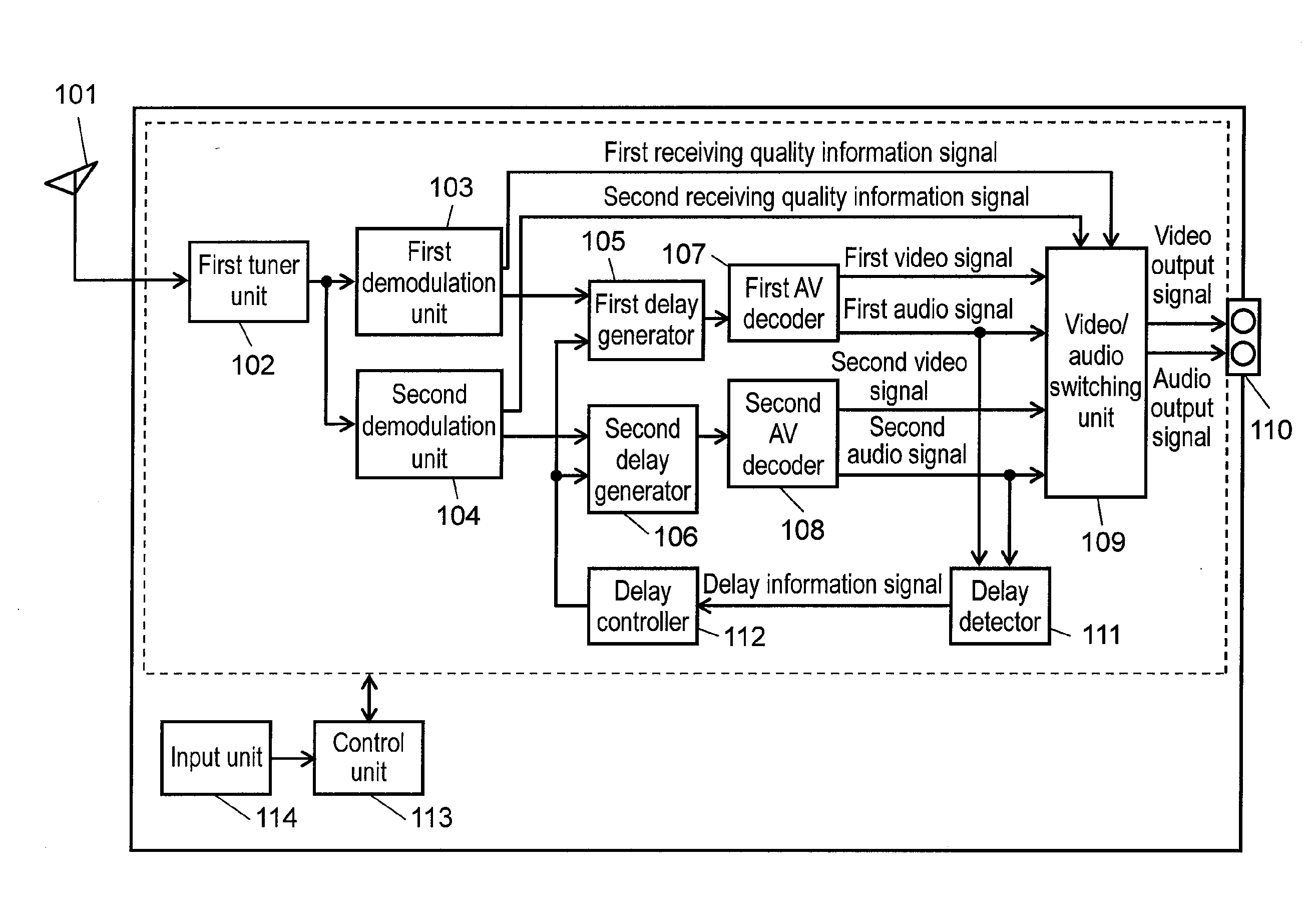
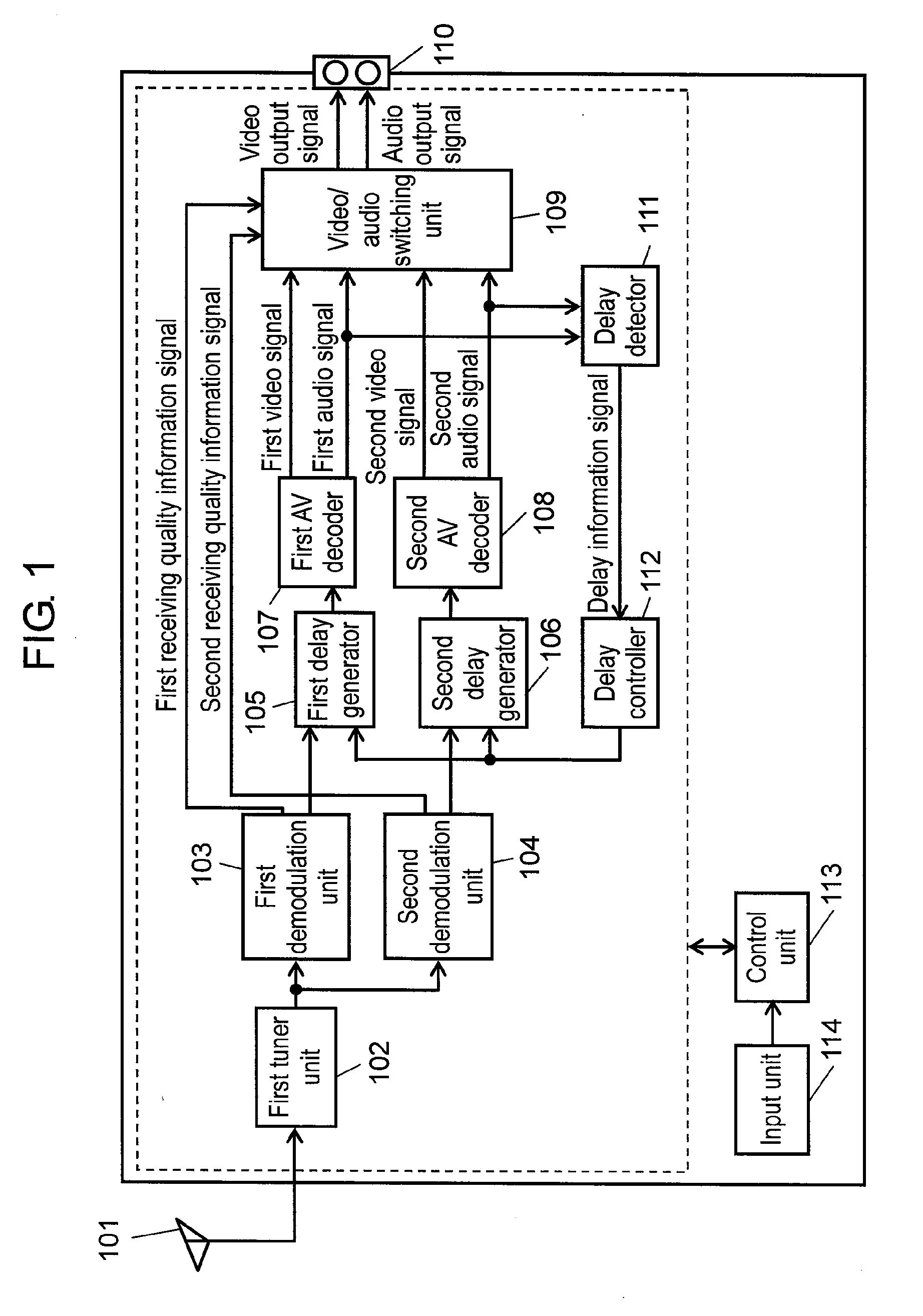
[0120]FIG. 1 is a block diagram showing a configuration of a receiver in accordance with a first exemplary embodiment of the present invention. As shown in FIG. 1, a receiver includes first antenna 101, first tuner unit 102, first demodulation unit 103, second demodulation unit 104, first delay generator 105, second delay generator 106, first AV decoder 107, second AV decoder 108, video / audio switching unit 109, video / audio output terminal 110, delay detector 111, delay controller 112, control unit 113, and input unit 114.
[0121]Next, an operation of the thus configured receiver in accordance with this exemplary embodiment is described. First tuner unit 102 channel-selects a received signal input from first antenna 101 and outputs the channel-selected signal to first demodulation unit 103 and second demodulation unit 104. First demodulation unit 103 demodulates the channel-selected signal output from first tuner unit 102 and outputs a first transport stream signal to first delay gene...
second exemplary embodiment
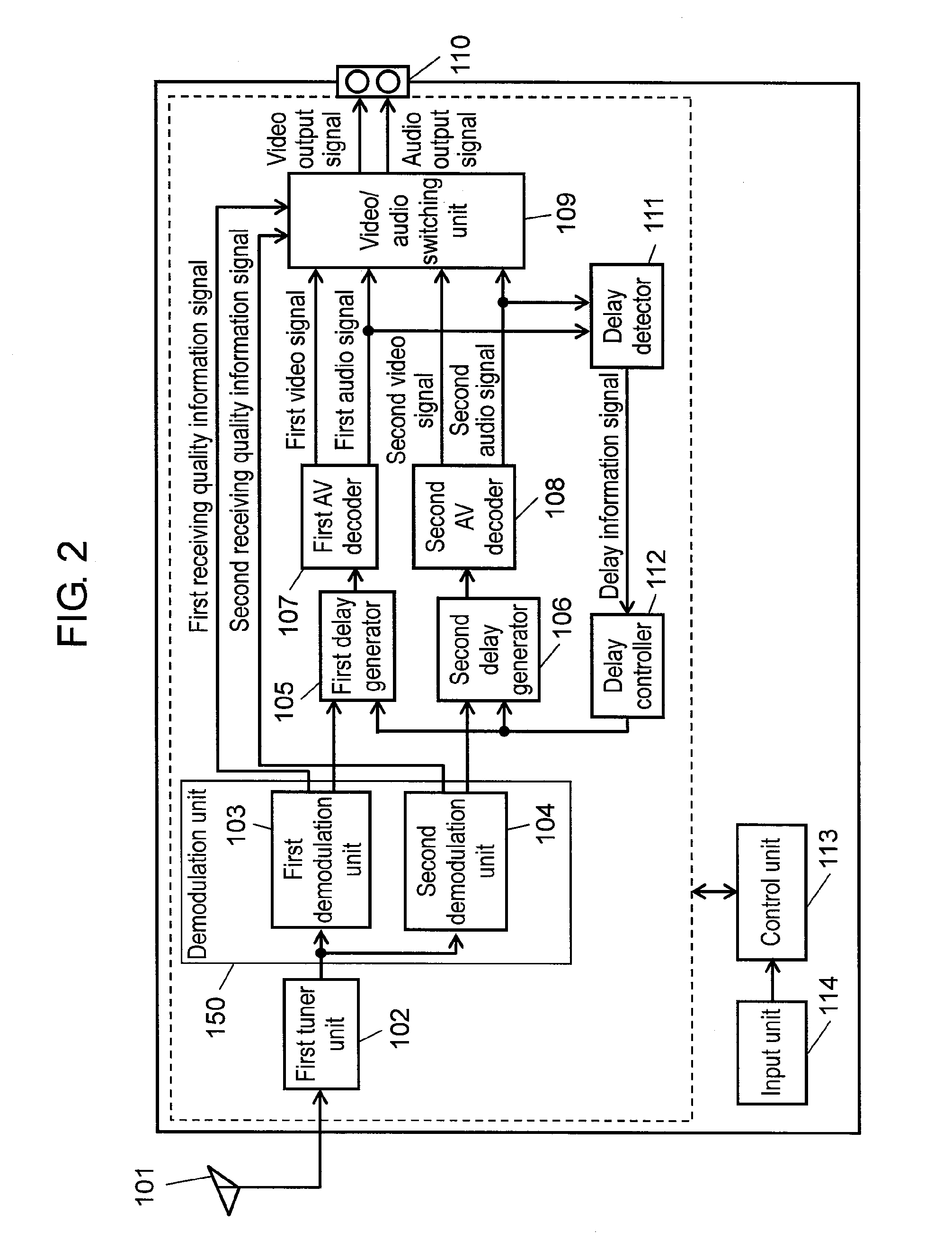
[0175]The first exemplary embodiment shows a configuration in which each delay generator delays coded signals of the video signal and the audio signal. However, a second exemplary embodiment shows a configuration that is different from the first exemplary embodiment in that AV decoded video signal and audio signal are delayed. Note here that detailed description of the same configurations and operations as those in the first exemplary embodiment are omitted.
[0176]FIG. 10 is a block diagram showing a configuration of a receiver in accordance with the second exemplary embodiment, which includes first delay generator 805 and second delay generator 806 for AV decoding the received signal and then delaying a video signal and an audio signal.
[0177]As shown in FIG. 10, the receiver of this exemplary embodiment includes first antenna 801, first tuner unit 802, first demodulation unit 803, second demodulation unit 804, first delay generator 805, second delay generator 806, first AV decoder 8...
third exemplary embodiment
[0193]In the first exemplary embodiment, in order to control the delay amount of each delay generator, timing information is detected from the delay amount of the audio signal output from the AV decoder. A third exemplary embodiment is different from the first exemplary embodiment in that a first timing information signal is output from first AV decoder 1107 and a second timing information signal is output from second AV decoder 1108 in order to control the delay amount of each delay generator. Note here that detailed description of the same configurations and operations as those in the first exemplary embodiment are omitted.
[0194]FIG. 14 is a block diagram showing a configuration of a receiver in accordance with the third exemplary embodiment. As shown in FIG. 14, the receiver of this exemplary embodiment includes first antenna 1101, first tuner unit 1102, first demodulation unit 1103, second demodulation unit 1104, first delay generator 1105, second delay generator 1106, first AV ...
PUM
 Abstract
Description
Claims
Application Information
 - R&D
- Intellectual Property
- Life Sciences
- Materials
- Tech Scout
- Unparalleled Data Quality
- Higher Quality Content
- 60% Fewer Hallucinations
Browse by: Latest US Patents, China's latest patents, Technical Efficacy Thesaurus, Application Domain, Technology Topic, Popular Technical Reports.
© 2025 PatSnap. All rights reserved.Legal|Privacy policy|Modern Slavery Act Transparency Statement|Sitemap|About US| Contact US: help@patsnap.com


