Molded polymeric drip edge

Inactive Publication Date: 2010-04-29
MITEK HLDG INC
View PDF22 Cites 20 Cited by
  • Summary
  • Abstract
  • Description
  • Claims
  • Application Information

AI Technical Summary

Benefits of technology

[0038]The drip edge device includes a hot melt adhesive which coats a surface of the drip edge device. The adhesive is selected for compatibility with a peel-and-stick installation, thus, upon pressure activation, when, for instance, the drip edge device with the hot melt adhesive thereon is pressed against th

Problems solved by technology

At that time the technology of pressure-sensitive hot melt adhesives needed for peel-and-stick applications was insufficiently developed.
Some critics indicated that the adhesive quality was insufficient for the rough masonry block surfaces.
Because of the presence of plasticizers, others were apprehensive about the available hot melt adhesives meeting the requisite fire retardancy standards.
However, these filled pressure-sensitive products had disadvantages, such as application problems, phase separation, toxicity, and reduced adhesion upon activation.
While, under ideal circumstances, these peel-and-stick materials were easy to apply, the patent literature indicates that these materials did not conform well to irregular surfaces.
Thus, the prior art bitumens used to secure these flashing materials to masonry walls often lacked the tackiness to bond tightly and durably to the wall surfaces.
On occasion, when circumstances were not ideal, the bituminous materials drooled marring the aesthetics of the brick veneer.
Despite these early efforts, developing the right combination of materials and methods for flashing cavity walls in a fast and efficient manner has proved elusive.
In

Method used


Image

  • Molded polymeric drip edge
  • Molded polymeric drip edge
  • Molded polymeric drip edge

Examples


Example

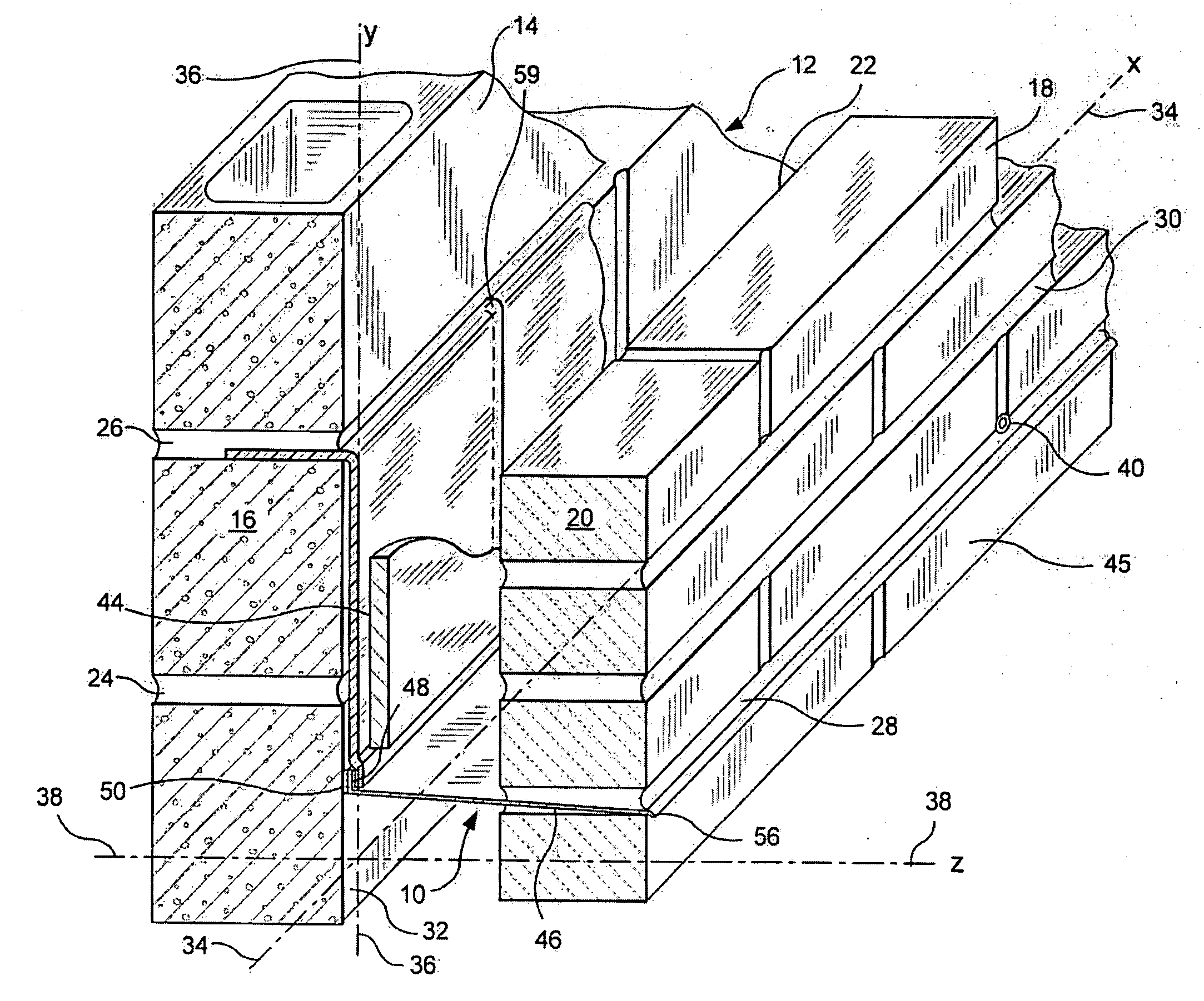
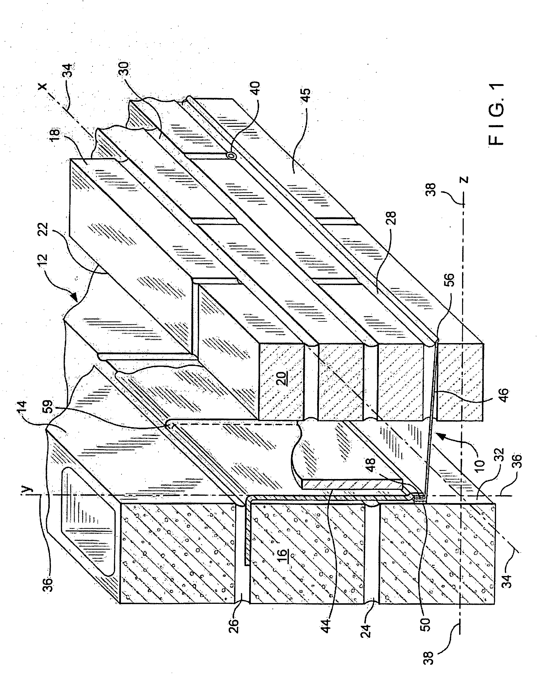
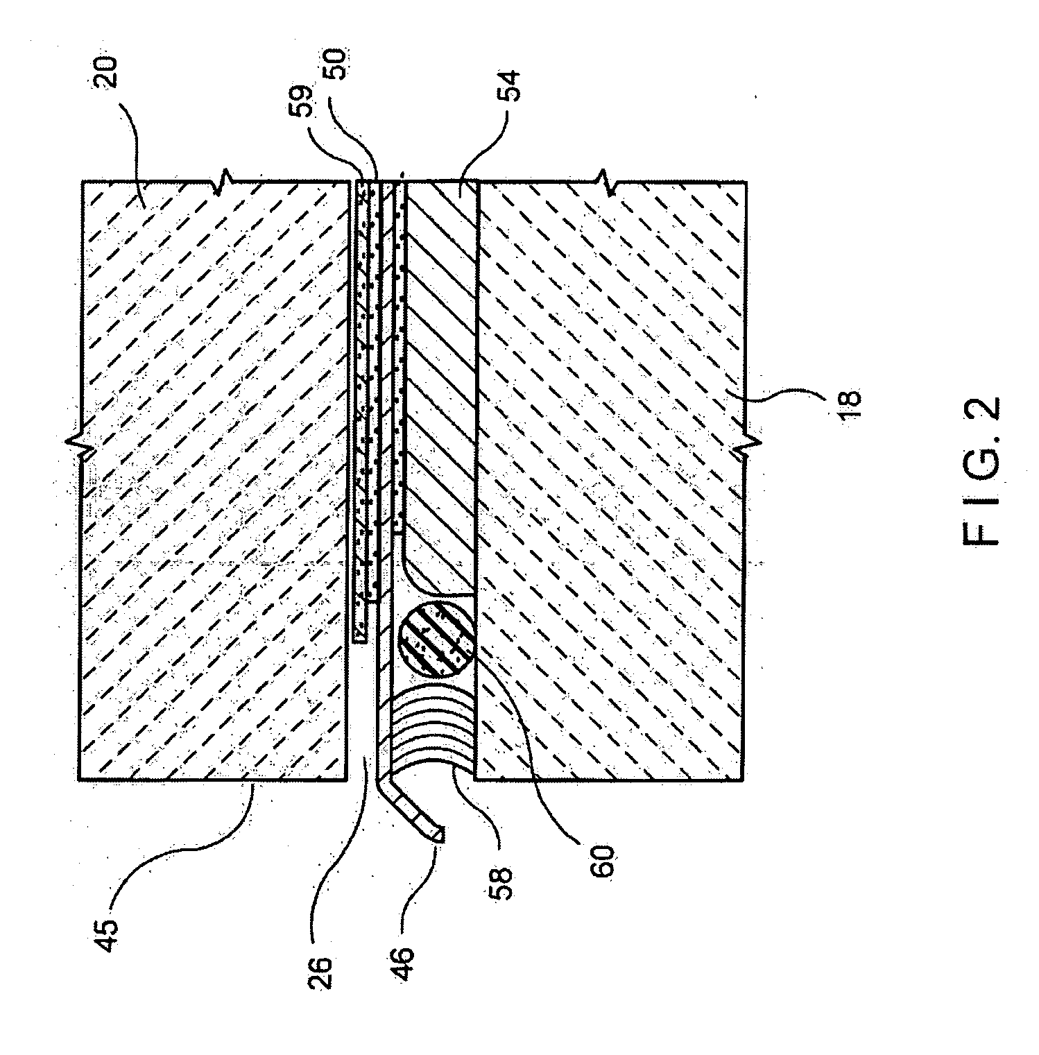
[0048]Referring now to FIGS. 1-3, views of the first embodiment of this invention in which a drainage system within a cavity wall structure, referred to generally by the reference designator 10, are shown. In this embodiment, a cavity wall structure 12 is shown having an inner wythe 14 of masonry blocks 16 and an outer wythe 18 of facing brick 20. Between the inner wythe 14 and the outer wythe 18, a cavity 22 is formed. Successive bed joints 24 and 26 are formed between courses of blocks 16 and the joints are substantially planar and horizontally disposed. Also, successive bed joints 28 and 30 are formed between courses of bricks 20 and the joints substantially planar and horizontally disposed. Selected bed joint 24 and bed joint 30 are constructed to align, that is to be substantially coplanar, the one with the other.

[0049]For purposes of this discussion, the exterior surface 32 of the inner wythe 14 contains a horizontal line or x-axis 34 and an intersecting vertical line or y-axi...

Example

[0064]Referring now to FIGS. 4 and 5, a perspective view of the second embodiment of this invention in which a surface-mounted drainage system, referred to generally by the reference designator 110, is shown. In this embodiment, similar parts to those of the first embodiment are referred to by reference designators 100 units higher than a similar part in the first embodiment. Thus, for example, the masonry block 16 in the first embodiment has an analogous masonry block 116 in the second embodiment. Here a cavity wall structure 112 is shown having an inner wythe 114 of masonry blocks 116 and an outer wythe 118 of facing brick 120. Between the inner wythe 114 and the outer wythe 118, a cavity 122 is formed and optional insulation 144 is shown. Successive bed joints 124 and 126 are formed between courses of blocks 116 and the joints are substantially planar and horizontally disposed. Also, successive bed joints 128 and 130 are formed between courses of bricks 120 and the joints are sub...


PUM


Abstract

A drip edge device is disclosed for use with the drainage system of a cavity wall structure. The drip edge device is disposed in the outer wythe, above the shelf angle or lintel, of a cavity wall structure extending the flashing and directing water and water vapor collected within the cavity wall to the weep holes and beyond the exterior surface of the outer wythe. The drip edge further allows for cavity wall ventilation. Removal of the water and the water vapor inhibits staining and material degradation. The drip edge device is a molded polymeric which withstands adverse environmental elements, including ultraviolet radiation. The drip edge device includes a peel-and-stick hot melt adhesive which, upon pressure activation, creates a durable bond with the rough surface of the masonry block or the flashing material. Optionally, a foam layer is placed on the lower surface of the drip edge.

Description

FIELD OF THE INVENTION[0001]This invention relates to a drip edge for use with a flashing system for a cavity wall structure, and more specifically to an improved molded polymeric drip edge that is an integral part of the flashing system.DESCRIPTION OF THE PRIOR ART[0002]In the past, investigations relating to cavity wall flashing systems for brick veneer masonry construction have been conducted. Flashing systems for cavity wall structures generally include flashing, weep holes and drip edges. While strides have been made in flashing-related technologies, including elastomeric materials and hot melt adhesives, there still remain several areas where continued development is ongoing.[0003]The inventor's patents and their assignee's product line are all related to accessories for cavity wall structures and include insulation, anchoring and seismic devices, and flashing and are sold under the trademarks of Seismiclip , Byna-Tie®, DW-10-X®, and FLEX-FLASH™. These products, which are manu...

Claims


Application Information

Patent Timeline
IPC IPC(8): E04B1/70E04C1/40
CPCE04B1/7046
Inventor HOHMANN, JR., RONALD P.
Owner MITEK HLDG INC
Why Eureka
Try Eureka