High-energy impact absorbing polycarbonate mounting method

a technology of high-energy impact and polycarbonate, which is applied in the direction of protective equipment, weapons, armour, etc., can solve the problems of dangling glass remnants, affecting the safety of workers, and affecting the safety of workers, and causing the damage of life and property

Active Publication Date: 2010-04-29
PLASKOLITE MASSACHUSETTS LLC +1
View PDF6 Cites 22 Cited by
  • Summary
  • Abstract
  • Description
  • Claims
  • Application Information

AI Technical Summary

Benefits of technology

[0013]This inventive method allows polycarbonate sheet or laminate to be used in high energy impa

Problems solved by technology

The explosive device carried in such vehicles is typically capable of generating a shock wave of sufficient force as to shear the face off unprotected buildings, leading to tremendous loss of life and property damage.
The resulting debris field surrounding the building is often several feet thick blocking entrances.
In addition, glass remnants dangle precariously, potentially falling from great heights to the ground in the slightest breeze.
Consequently, both hazards hinder and threaten the safety of emergency response teams as they attempt to enter the damaged building to render aid to

Method used


Image

  • High-energy impact absorbing polycarbonate mounting method
  • High-energy impact absorbing polycarbonate mounting method
  • High-energy impact absorbing polycarbonate mounting method

Examples


examples

[0053]The present invention is further illustrated, but is not to be limited, by the following examples.

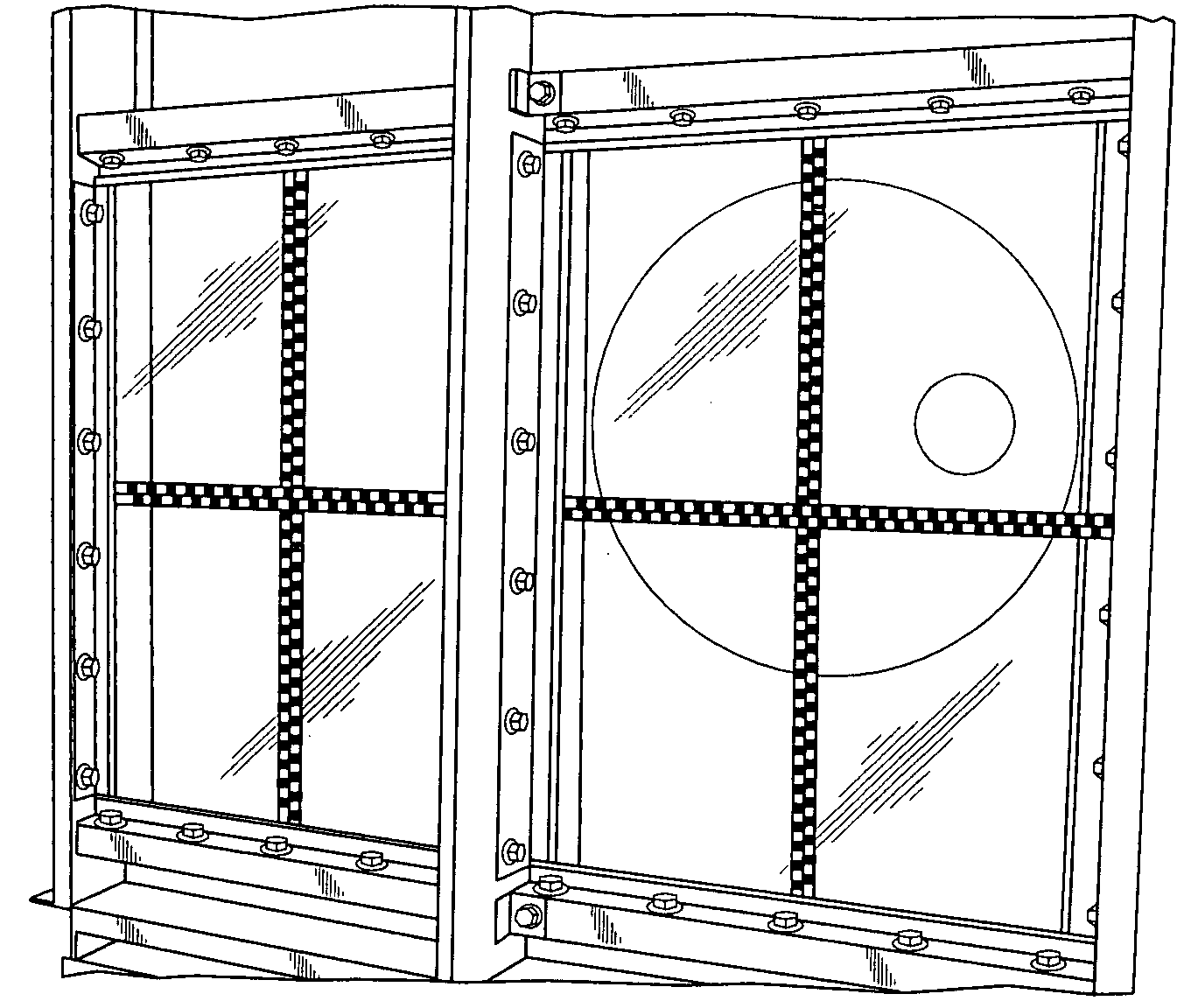
[0054]Two 48 inch by 66 inch, 0.375 inch thick transparent monolithic polycarbonate panels were mounted to a traditional, non-active (non-flexing) frame and fastened to a shock tube as shown in FIG. 4. The polycarbonate panels were wet-glazed into the frame using an industry standard silicone. The panels both had an abrasion-resistant hard-coat applied to the surfaces. The panels were tested at near DOD (U.S. Department of Defense) loads of 6.5 psi and 61 psi-msec, pressure and impulse, respectively. Both panels failed catastrophically as shown in FIG. 5.

[0055]However, when the same panels were mounted according to the inventive bi-active framing method where the two longer sides were attached through cylindrical hardware to semi-rigid (flexing) metal frame sections, computer simulation predicted only a minor crack in the panel, as shown in FIG. 6 (a quarter-symmetric model). This...


PUM

PropertyMeasurementUnit
Thicknessaaaaaaaaaa
Thicknessaaaaaaaaaa
Lengthaaaaaaaaaa

Abstract

The present invention provides a bi-active method of mounting a monolithic polycarbonate sheet or a laminate in a semi-rigid metallic framing system along two parallel sides of a rectangular shaped sheet or laminate with the two shorter parallel sides being unconstrained. In the case of a square shaped sheet, two parallel sides are supported in the semi-rigid frame, and the other two parallel sides are unconstrained. The semi-rigid frame utilizes cylindrically shaped hardware (i.e., bolts, rivets, studs, etc.) to hold the sheet or laminate. The semi-rigid frame is designed, via section and material properties, to flex and hinge about fixed mounting points along the length of the frame.

Description

FIELD OF THE INVENTION[0001]The present invention relates to a method of mounting a blast-resistant barrier such as a barrier comprising at least one high energy impact absorbing polycarbonate panel.BACKGROUND OF THE INVENTION[0002]Government and commercial buildings (e.g., embassies, court houses, hotels, casinos, malls, airports and stadiums) have proven attractive targets for bombing attacks throughout the world in recent years. The attacker, in most cases, is a politically motivated terrorist using, as a weapon, a high explosive device transported and detonated inside a vehicle nearby the targeted building. The explosive device carried in such vehicles is typically capable of generating a shock wave of sufficient force as to shear the face off unprotected buildings, leading to tremendous loss of life and property damage. The resulting debris field surrounding the building is often several feet thick blocking entrances. In addition, glass remnants dangle precariously, potentially...

Claims


Application Information

Patent Timeline
IPC IPC(8): F41H5/24
CPCF41H5/0407F41H5/24F41H5/263F41H5/013E04H9/10E04C2/384E04C2/20A62C2/06E06B3/76E06B3/78E06B5/16
Inventor LORENZO, JAMES M.PYLES, ROBERT A.GOODSON, RAYMOND L.
Owner PLASKOLITE MASSACHUSETTS LLC
Why Eureka
Try Eureka