Reciprocating vibration generator

Active Publication Date: 2010-04-29
SANYO SEIMITSU
View PDF9 Cites 20 Cited by
  • Summary
  • Abstract
  • Description
  • Claims
  • Application Information

AI Technical Summary

Benefits of technology

[0012]The ring-shaped permanent magnet may also be a single ring-shaped permanent magnet magnetized in a radial direction from the ring-shaped center, but to facilitate magnetization, it may also be comprised of a pair of semi-ring-shaped permanent magnets fit at the inner circumference side of the ring-shaped weight with magnetic poles facing each other. When the semi-ring-shaped permanent magnets a

Problems solved by technology

In the above vibroacoustic converter, collision of the bottom yoke plate forming the reciprocating vibrating body and the plate facing this can be absorbed by the magnetic fluid, but when mounting a vibroacoustic converter in a mobile phone, the reciprocating vibrating body shakes in a di

Method used


Image

  • Reciprocating vibration generator
  • Reciprocating vibration generator
  • Reciprocating vibration generator

Examples


first embodiment

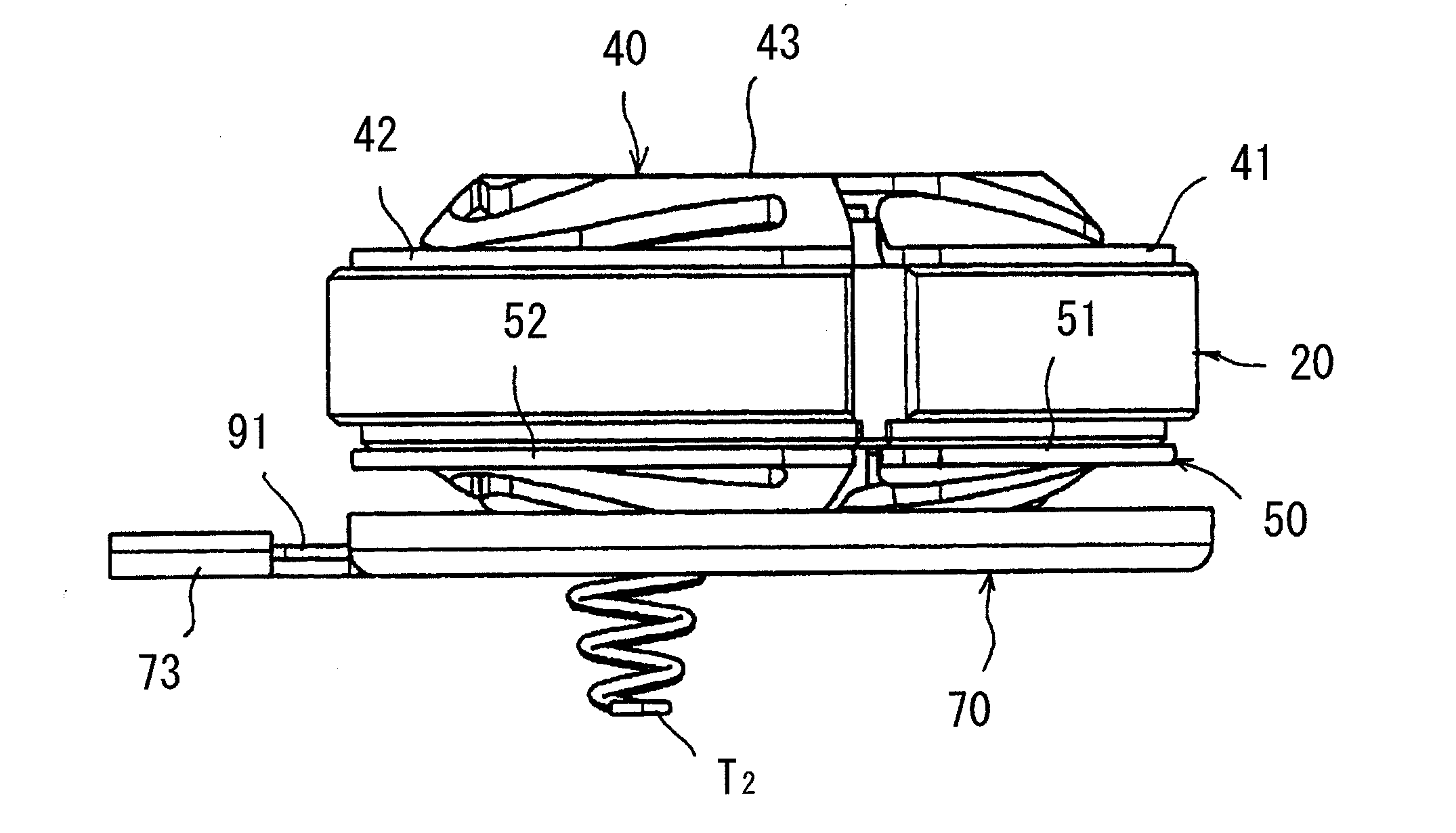
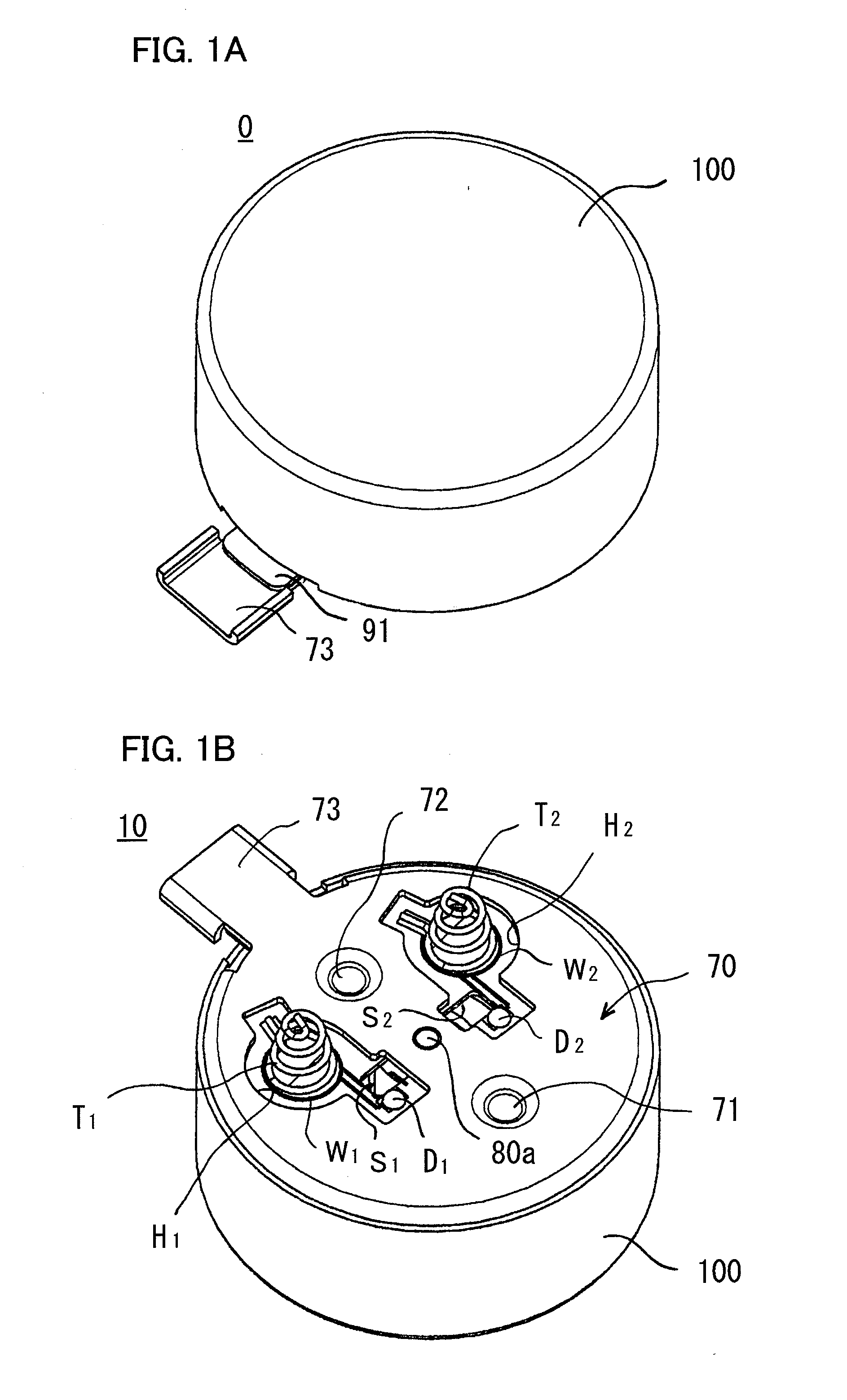
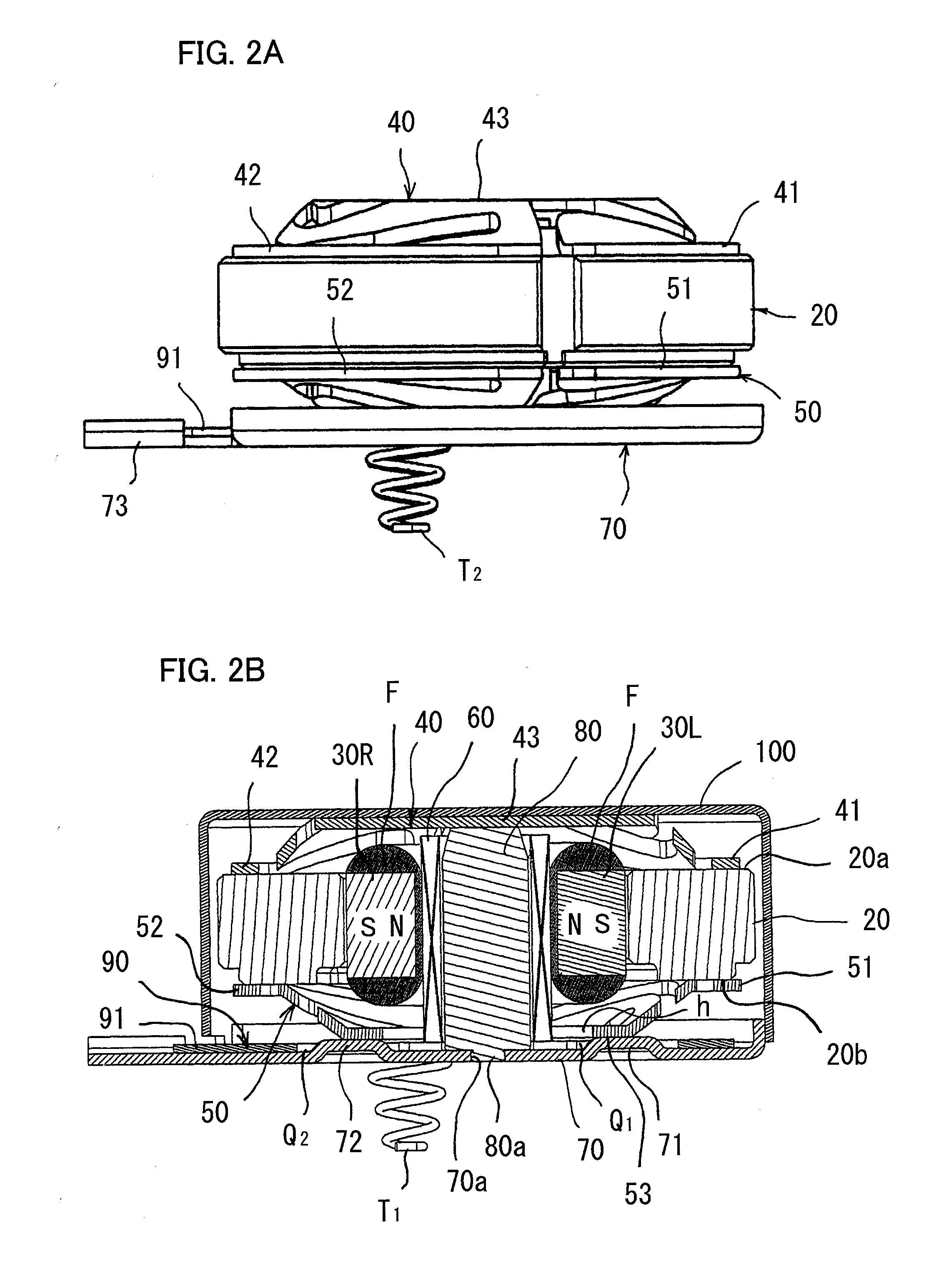
[0026]FIG. 1A is a perspective view showing a vibration linear actuator according a first embodiment of the present invention; FIG. 1B is a perspective viewing showing an upside down state of the same vibration linear actuator; FIG. 2A is a side view showing the state with a case body of the same vibration linear actuator detached; FIG. 2B is a longitudinal cross-sectional side view of the same vibration linear actuator; FIG. 3A is a plan view showing the state with a case of the same vibration linear actuator detached; FIG. 3B is a bottom view of the same vibration linear actuator; FIG. 4 is a perspective view of the assembly of the same vibration linear actuator seen from above; FIG. 5 is a perspective view of the assembly of the same vibration linear actuator seen from below; FIG. 6A is a perspective view showing the reciprocating vibrating body and lower plate spring of the same vibration linear actuator seen from the back; and FIG. 6B is a bottom view showing the same reciproca...

second embodiment

[0038]FIG. 8 is a longitudinal cross-sectional side view showing a vibration linear actuator according to an embodiment of the present invention 2. The vibration linear actuator 200 of this embodiment is a vibroacoustic converter equipped with a speaker function. It has a flat cup-shaped lower case body 110 for holding the reciprocating vibrating body and has a shared yoke 120. The part from this shared yoke 120 to the cover 130 of the sound hole 130a forms a speaker part.

[0039]The reciprocating vibrating body has a ring-shaped weight 20′ and a ring-shaped permanent magnet 30 comprised of a parallel magnetized pair of semi-ring-shaped permanent magnets 30R, 30L fit at the inner circumference side with the same magnetic poles facing each other. The plate spring of this embodiment is only the lower plate spring 50′. This is attached by inserting the center shaft M into the center hole K and positioning hole 110a and has elastic pieces 51′, 52′ supporting the ring-shaped weight 20′. Th...


PUM


Abstract

A reciprocating vibration generator of a structure enabling force of a reciprocating vibrating body striking a coil to be absorbed by magnetic fluid even if an external impact force is applied, that is, a reciprocating vibration generator provided in a case body 100 with an upper plate spring 40 and a lower plate spring 50 for supporting a ring-shaped weight 20 having a ring-shaped permanent magnet 30 comprised of a combination of semi-ring-shaped permanent magnets 30R, 30L at its inner circumference side so as to be able to reciprocally vibrate in a vertical direction and a cylindrical excitation coil 60 passing through the inside of the ring-shaped permanent magnet 30 in the vertical direction and generating a reciprocating vibrating magnetic field, wherein the semi-ring-shaped permanent magnets 30R, 30L are magnetized in a direction spanning the inner circumferential surface and outer circumferential surface, the inner circumferential surface and top and bottom end faces of the semi-ring-shaped permanent magnet 30R, 30L are covered by magnetic fluid F, and a gap between the inner circumferential surface and the outer circumferential surface of the excitation coil 60 is filled with magnetic fluid F.

Description

CROSS-REFERENCE TO RELATED APPLICATIONS[0001]This application is based upon and claims the benefit of priority of the prior Japanese Patent Application No. 2008-276547, filed on Oct. 28, 2008, the entire contents of which are incorporated herein by reference.BACKGROUND OF THE INVENTION[0002]1. Field of the Invention[0003]The present invention relates to a reciprocating vibration generator used for a mobile phone etc., more particularly relates to a reciprocating vibration generator having a reciprocating vibrating body.[0004]2. Description of the Related Art[0005]For example, a vibroacoustic converter disclosed in Japanese Patent Publication (A) No. 2002-263578 is provided with a sound generating vibration plate with an outside end fastened to a top end of a cylindrical case, a plate fastening the outside end to the bottom end of the case, two plate springs supporting a ring-shaped weight to be able to reciprocate up and down, a bottom yoke plate fastened to an inner circumferential...

Claims


Application Information

Patent Timeline
IPC IPC(8): H02K33/00
CPCH02K33/16
Inventor MASAMI, YAMAZAKIKEISUKE, FURUICHIHIROKI, KATOU
Owner SANYO SEIMITSU
Why Eureka
Try Eureka