Method of manufacturing rare-earth magnets

a rare earth magnet and manufacturing method technology, applied in the field of rare earth magnet manufacturing, can solve the problems of insufficient increase of coercive force and inability to suppress the coarsening of crystal grains, and achieve the effects of high coercive force, high magnetization, and increased coercive for

Inactive Publication Date: 2014-10-16
TOYOTA JIDOSHA KK
View PDF6 Cites 11 Cited by
  • Summary
  • Abstract
  • Description
  • Claims
  • Application Information

AI Technical Summary

Benefits of technology

[0018]The method of manufacturing' rare-earth magnets according to the invention includes: a first step of producing a compact by subjecting a sintered body, which is formed of a RE—Fe—B main phase having a nanocrystalline structure (where RE is at least one of neodymium and praseodymium) and a grain boundary phase of an RE—X alloy (where X is a metal element) located around the main phase, to hot plastic processing that imparts anisotropy; and a second step of producing a rare-earth magnet by melting a RE—Y—Z alloy which increases the coercive force of the compact (where Y is a transition metal element and Z is a heavy rare-earth element), together with the grain boundary phase, and liquid-phase infiltrating the RE—Y—Z alloy melt from a surface of the compact.
[0024]Next, the grain boundary phase making up this compact is melted, thus causing a RE—Y—Z alloy (wherein Y is a transition metal element, and Z is a heavy rare-earth element), which is a modified alloy, to liquid-phase infiltrate the compact from the surface thereof. The RE—Y—Z alloy melt thereby infiltrates into the molten-state grain boundary phase of the compact and, while giving rise to structural changes at the interior of the compact, produces a rare-earth magnet having an increased coercive force.
[0025]By selecting, as the molten-state RE—Y—Z alloy to be liquid-phase infiltrated from the surface of the compact into the liquid-state grain boundary phase, a Nd alloy having a melting point similar to that of the grain boundary phase, a melt of the Nd alloy in the range of about 600° C. to about 650° C. infiltrates into the molten-state grain boundary phase. As a result, compared to a case in which a Dy—Cu alloy or the like is solid-phase diffused within the grain boundary phase, the diffusion efficiency and rate of diffusion rise markedly, enabling diffusion of the modified alloy to be achieved in a short time.
[0026]It was discovered that, by using a Re—Y—Z alloy (wherein Y is a transition metal element, and Z is a heavy rare-earth element), the melting point can be greatly lowered compared with cases in which a heavy rare-earth element such as Dy is diffused and infiltrated alone as in conventional manufacturing methods, and cases in which an alloy of a transition metal element and a heavy rare-earth element, such as a Dy—Cu alloy, is diffused and infiltrated.
[0028]By using a RE—Y—Z alloy (wherein Y is a transition metal element, and Z is a heavy rare-earth element), compared to cases up until now in which a Dy alloy or the like is diffused and infiltrated in an high-temperature atmosphere of at least 1000° C., infiltration of a modified alloy can be carried out under much lower temperature conditions of about 600° C. As a result, coarsening of the main phase (crystalline grains) can be suppressed, which also contributes to an increase in the coercive force. In particular, infiltration of a modified alloy under temperature conditions of about 600° C. may also be regarded as desirable because nanocrystalline magnets, unlike sintered magnets, undergo pronounced coarsening of the crystal grains when placed for about 10 minutes in a high-temperature atmosphere of about 800° C. Even in cases where a 70Dy-30Cu alloy is used, because this has a melting point of 790° C., high-temperature treatment of about 800° C. is required, making it impossible to suppress coarsening of the crystal grains.
[0032]As can be appreciated from the foregoing description, the inventive method of manufacturing rare-earth magnets uses a RE—Y—Z alloy (wherein Y is a transition metal element, and Z is a heavy rare-earth element), which is a low-melting modified alloy, to liquid-phase infiltrate a modified alloy melt into the molten-state grain boundary phase of a compact obtained by subjecting a sintered body composed of a RE—Fe—B main phase (wherein RE is at least, one of Nd and Pr) having a nanocrystalline structure and a grain boundary phase of RE—X alloy located around the main phase to hot plastic working. As a result, coarsening of the nanocrystalline grains making up the main phase can be suppressed, enabling magnetic decoupling between the nanocrystalline grains to be precisely achieved in the modified grain boundary phase, and thus making it possible to manufacture rare-earth magnets which also have a good magnetization.

Problems solved by technology

Hence, one key challenge has been to develop low-dysprosium magnets which ensure coercive force performance while reducing the amount of dysprosium, and dysprosium-free magnets which ensure coercive force performance without the use of any dysprosium.
That is, even though dysprosium and terbium are grain boundary diffused, it becomes impossible to sufficiently increase the coercive force.
As a result, it is impossible to suppress a coarsening of the crystal grains.

Method used


Image

  • Method of manufacturing rare-earth magnets
  • Method of manufacturing rare-earth magnets
  • Method of manufacturing rare-earth magnets

Examples


Embodiment Construction

[0038]Embodiments of the inventive method of manufacturing rare-earth magnets are described below in conjunction with the attached diagrams.

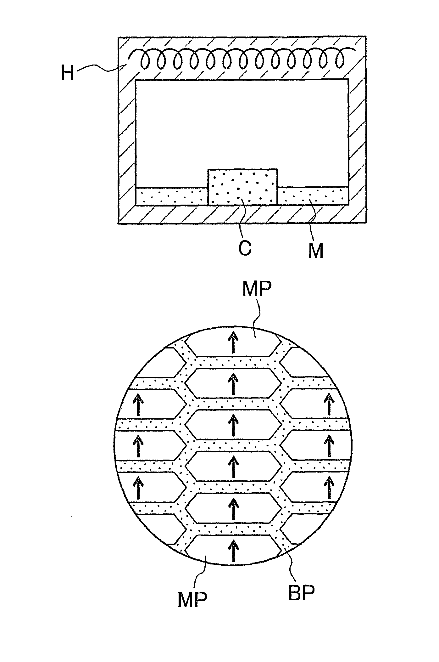
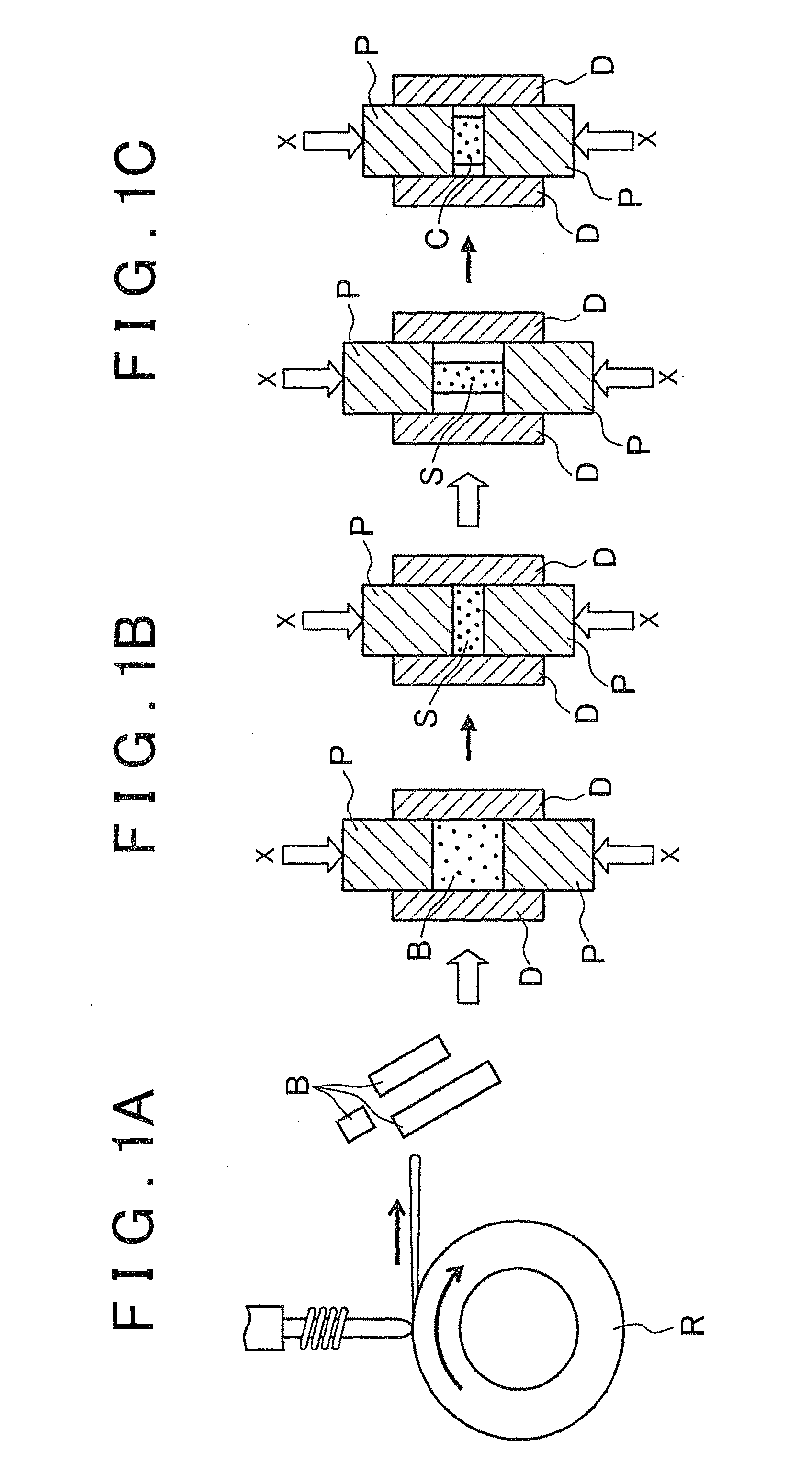
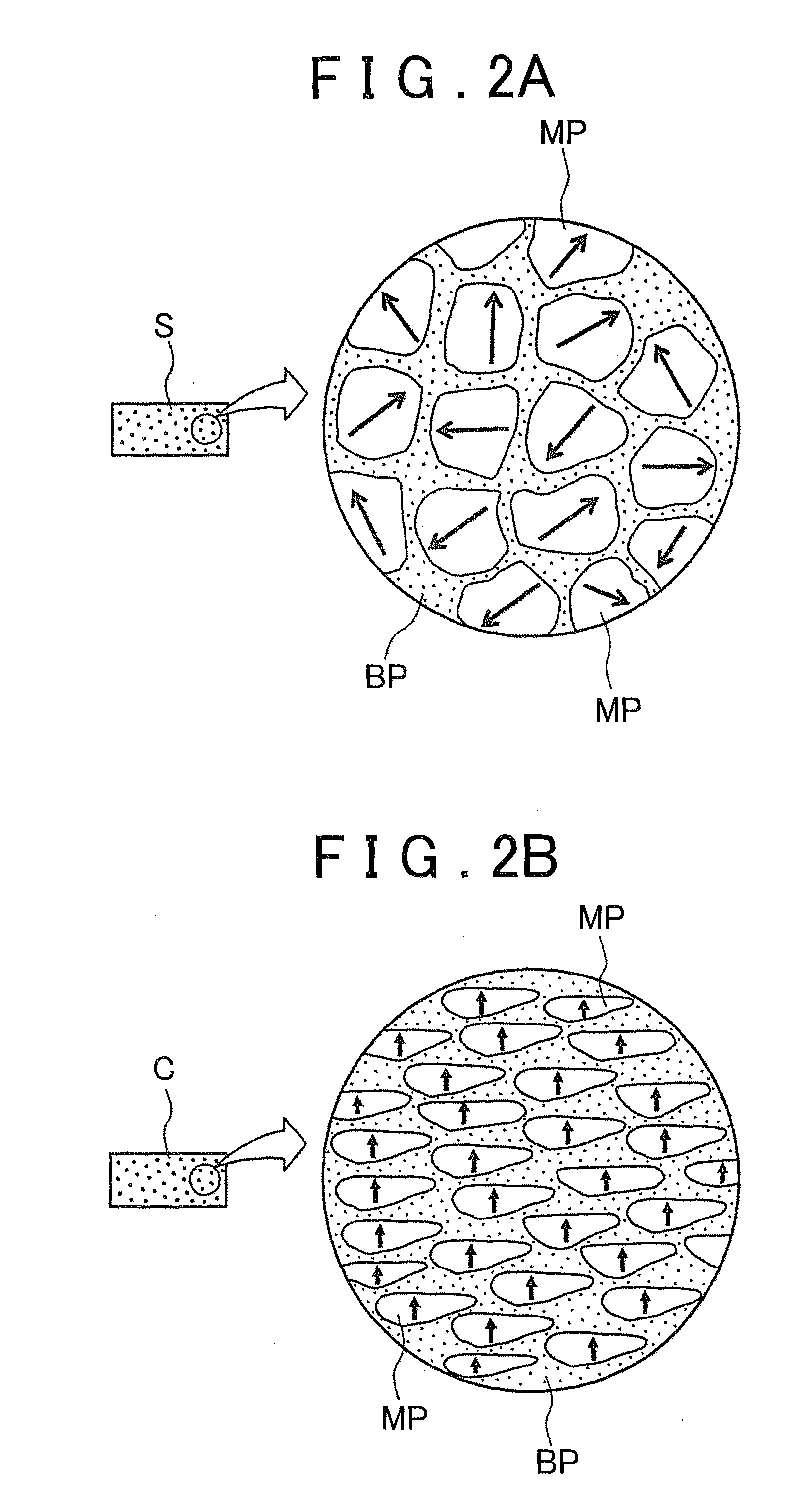
[0039]FIGS. 1A, 1B and 1C are schematic diagrams illustrating the first step in an embodiment of the inventive method of manufacturing a rare-earth magnet, and FIG. 3A is a diagram illustrating the second step in the inventive method of manufacturing rare-earth magnets. Also, FIG. 2A is a diagram depicting the microstructure of the sintered body shown in FIG. 1B, and FIG. 2B is a diagram depicting the microstructure of the compact in FIG. 1C. In addition, FIG. 3B is a diagram depicting the microstructure of a rare-earth magnet during modification of the structure with a modified alloy, and FIG. 3C is a diagram depicting the microstructure of a rare-earth magnet in which modification of the structure with a modified alloy is complete.

[0040]As shown in FIG. 1A, an alloy ingot is high-frequency induction melted by a single-roll melt spinning proces...


PUM

PropertyMeasurementUnit
grain sizesaaaaaaaaaa
temperatureaaaaaaaaaa

Abstract

A method of manufacturing rare-earth magnets includes, a first step of producing a compact C by subjecting a sintered body S, which is formed of a RE—Fe—B main phase MP having a nanocrystalline structure (where RE is at least one of neodymium and praseodymium) and a grain boundary phase BP of an RE—X alloy (where X is a metal element) located around the main phase, to hot plastic processing that imparts anisotropy; and a second step of producing a rare-earth magnet RM by melting a RE—Y—Z alloy which increases the coercive force of the compact C (where Y is a transition metal element, and Z is a heavy rare-earth element), together with the grain boundary phase BP, and liquid-phase infiltrating the RE—Y—Z alloy melt from a surface of the compact C.

Description

BACKGROUND OF THE INVENTION[0001]1. Field of the Invention[0002]The invention relates to a method of manufacturing rare-earth magnets.[0003]2. Description of Related Art[0004]Rare-earth magnets which use rare-earth elements such as lanthanoids are also called permanent magnets. Applications include motors in hard disk drives and magnetic resonance imaging (MRI) scanners, as well as drive motors in hybrid vehicles and electric cars.[0005]Remanent magnetization (remanent magnetic flux density) and coercive force may be cited as indicators of the performance of these rare-earth magnets. The rise in heat generation associated with the miniaturization and trend toward higher current density in motors has prompted a greater desire for heat resistance also in the rare-earth magnets that are, used. How to maintain the coercive strength of a magnet under high-temperature use is thus a major topic of research today in this technical field. In the case of Nd—Fe—B-based magnets, for example, wh...

Claims


Application Information

Patent Timeline
Patent Type & Authority Applications(United States)
IPC IPC(8): H01F41/02
CPCH01F41/02H01F1/0571H01F1/0577H01F41/0293C22C28/00C22C45/00C22C2202/02B22F1/07C22C1/11
Inventor SHOJI, TETSUYAOMURA, SHINYAHIRAOKA, MOTOKI
Owner TOYOTA JIDOSHA KK
Why Eureka
Try Eureka