Radar system

a radar and system technology, applied in the field of radar systems, can solve the problems of radar not being able to detect a vehicle, radar having a radio wave interference problem with another, and the radar system cannot detect a vehicle, so as to achieve the effect of preventing radio wave interferen

Active Publication Date: 2010-04-29
TOYOTA JIDOSHA KK
View PDF22 Cites 27 Cited by
  • Summary
  • Abstract
  • Description
  • Claims
  • Application Information

AI Technical Summary

Benefits of technology

[0008]The invention provides a radar system that effectivel...

Problems solved by technology

It is generally known that a radar system, when using a CW mode, is not able to detect a vehicle (an example of an obstacle) when a relative velocity with respect to the vehicle is zero.
In addition, such a radar has a problem in radio wave interference with another vehicle, or the like (see JP-A-2007-187632, JP-A-2002-14159, JP-A-2004-69693, JP-A-2006-242818 and JP-A-2007-155551).
However, when one and the same...

Method used


Image

  • Radar system
  • Radar system
  • Radar system

Examples


first embodiment

[0041]Hereinafter, a radar system according to the invention will be described with reference to the accompanying drawings.

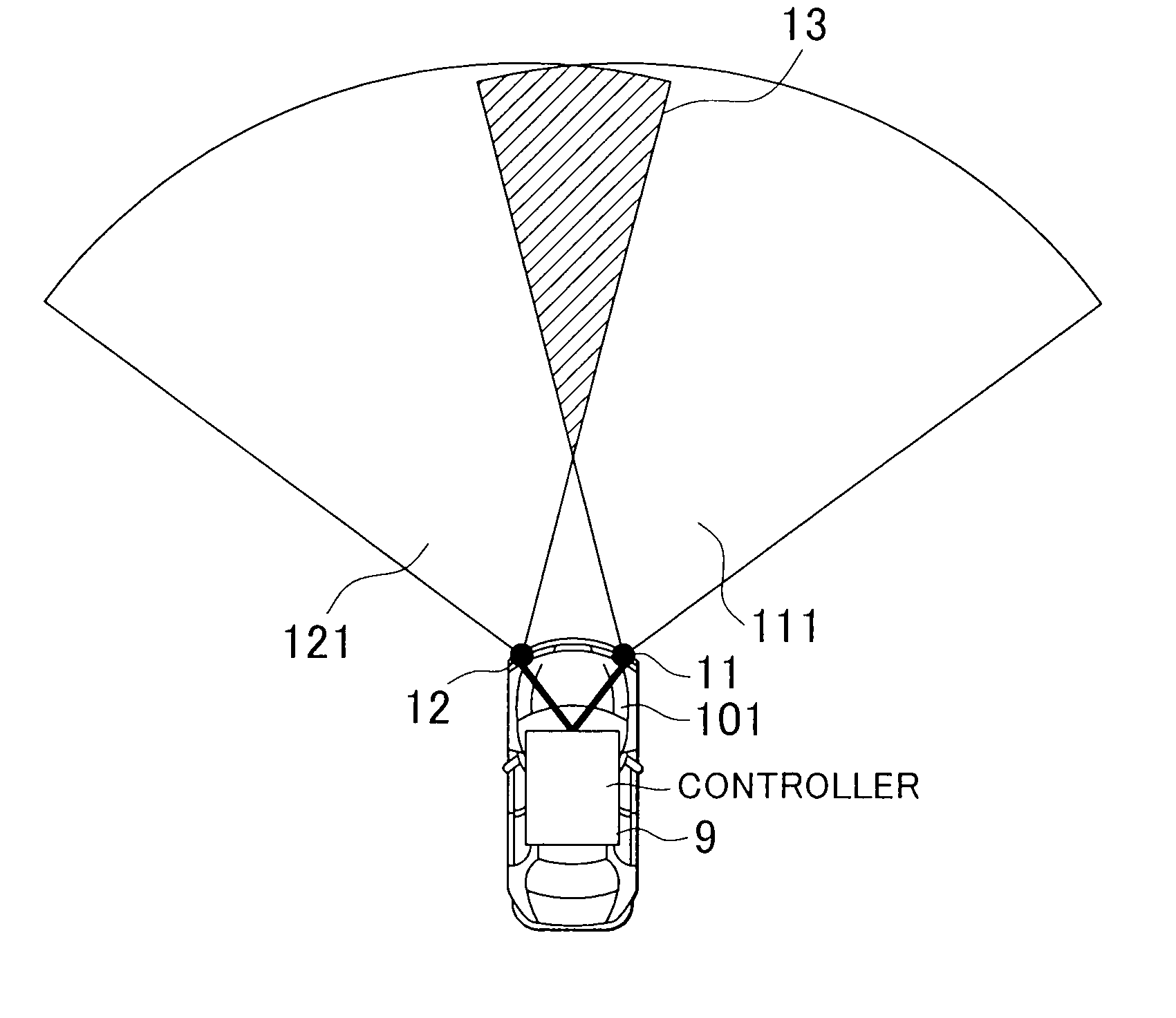
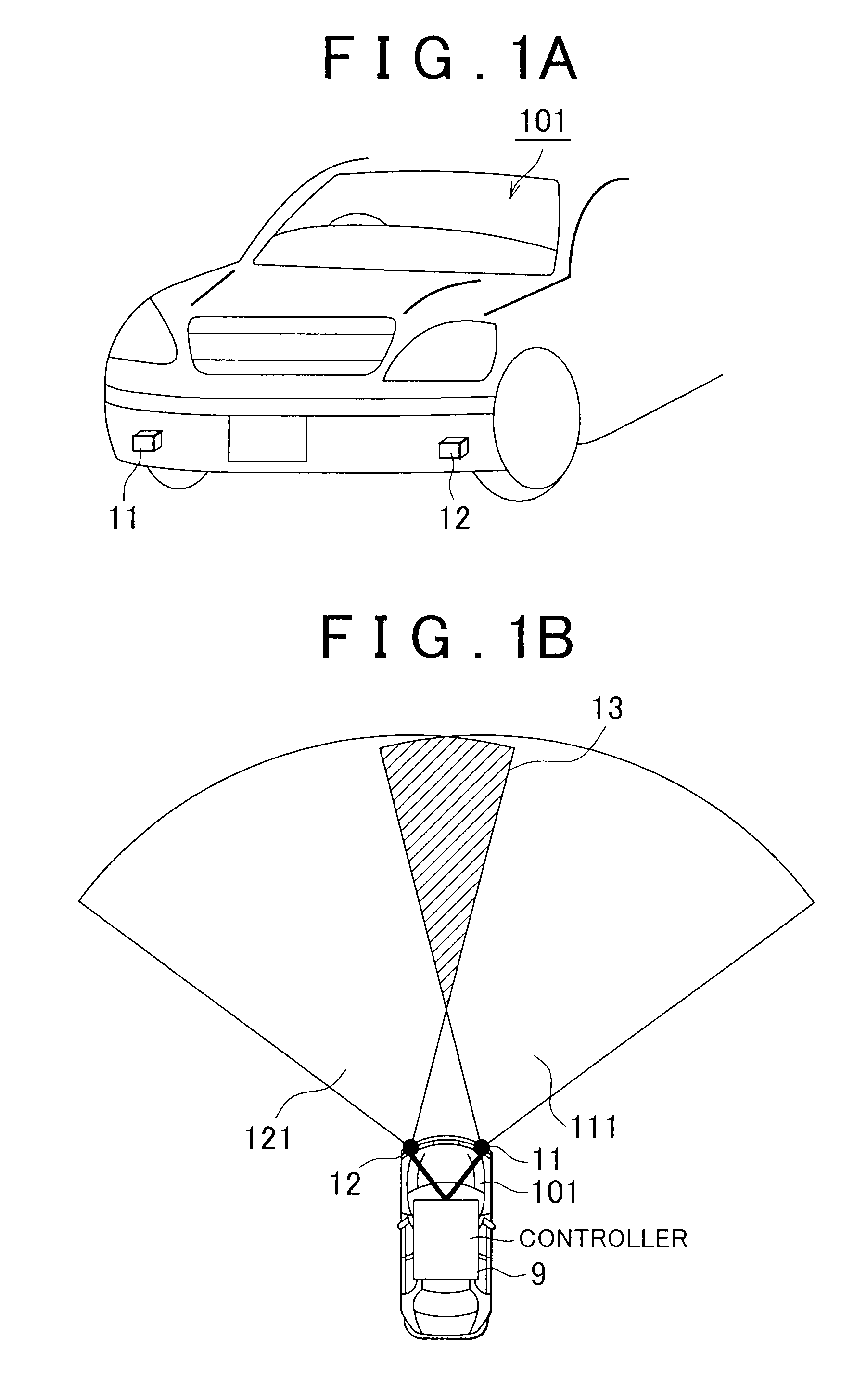
[0042]FIG. 1A and FIG. 1B are external views of radars according to the first embodiment of the invention. FIG. 1A shows arrangement of the radars as viewed from the front of a vehicle 101. FIG. 1B shows ranges 111 and 112 of detection of the radars 11 and 12 as viewed from the upper side of the vehicle 101.

[0043]As shown in FIG. 1A, the vehicle 101 is equipped with a radar system (which corresponds to a radar system 1 shown in FIG. 2). The radar system includes the plurality of radars 11 and 12 (in this application, when simply referred to a radar, it indicates not the whole radar system but the radar equipped for the radar system). The radar 11 and the radar 12 each output a distance to an object ahead and a relative velocity of the object to an external component. The radars 11 and 12 are, for example, provided at both ends of the front of the vehicle 101. A ...

third embodiment

[0062]Note that it is also applicable that the maximum frequency FFH of the FM-CW mode 3 used in the radar 11 coincides with the maximum frequency of the CW mode 4 used in the radar 12. In this case as well, a similar advantageous effect to that of the third embodiment may be obtained. In addition, both the maximum frequency and minimum frequency of the FM-CW mode 3 used in the radar 11 may respectively coincide with both the maximum frequency and minimum frequency of the CW mode 4 used in the radar 12.

[0063]FIG. 3D shows the fourth embodiment of the frequency modulation patterns of radio waves. Because of the same reason as described in the third embodiment, the fourth embodiment differs from the first embodiment in that the controller 9 causes the minimum value of the frequency band of the FM-CW mode 3 used in the radar 11 to coincide with the maximum value of the frequency band of the CW mode 4 used in the radar 12. With the above configuration, it is possible to reduce the frequ...

sixth embodiment

[0066]FIG. 4B shows the frequency modulation patterns of radio waves. The radar 12 constantly transmits a radio wave. As shown by the waveforms 36 and 46, the controller 9 outputs radio waves in accordance with the following conditions.

[0067]In a time period during which the frequencies (FFL to FFU) output in the FM-CW mode 3 by the radar 11 are higher than a predetermined frequency FM in the middle of the frequencies, the radar 12 outputs a certain frequency FCL (between FFL and FM) that is lower than FM (this is the first condition).

[0068]In a time period during which the frequencies (FFL to FFU) output in the FM-CW mode 3 by the radar 11 are lower than the frequency FM, the radar 12 outputs a certain frequency FCH (between FM and FCH) that is higher than FM (this is the second condition).

[0069]With the above configuration, it is possible to configure the FM-CW mode 3 and the CW mode 4 so that there is no time at which the frequencies coincide with each other. That is, the radars ...


PUM


Abstract

A radar system includes radars and a controller. The controller controls waveform patterns of the radars. As a signal processing unit of each of the radars receives an instruction from the controller, the signal processing unit selects a frequency modulation pattern of a VCO between an FM-CW mode and a CW mode stored in a waveform memory to perform mode switching, and then outputs a radio wave from a transmission antenna. Then, the controller instructs each signal processing unit for a frequency modulation pattern of each radar or an output timing of each pattern so that a time, at which continuous wave signals output from the radars have the same frequency, is not continuous.

Description

INCORPORATION BY REFERENCE[0001]The disclosure of Japanese Patent Application No. 2008-276867 filed on Oct. 28, 2008 including the specification, drawings and abstract is incorporated herein by reference in its entirety.BACKGROUND OF THE INVENTION[0002]1. Field of the Invention[0003]The invention relates to a technique for preventing radio wave interference between a plurality of radars.[0004]2. Description of the Related Art[0005]A vehicle (mobile unit) equipped with a radar at the front or rear thereof is practically used. The radar is able to detect an obstacle, and acquires a distance to the obstacle and a relative velocity of the obstacle. With the above configuration, the vehicle is able to avoid a collision with the obstacle or warn a driver of the collision. A known waveform of a radio wave output from such a radar, for example, includes an FM-CW mode of a frequency modulation pattern in which the frequency is increased or decreased along a triangular wave and a CW mode in w...

Claims


Application Information

Patent Timeline
IPC IPC(8): G01S13/00G01S13/93G01S13/931
CPCG01S7/023G01S13/345G01S13/347G01S2013/9389G01S13/931G01S2013/9375G01S13/348G01S2013/93271G01S2013/93275G01S7/0232G01S7/0233G01S13/87
Inventor OGAWA, MASARU
Owner TOYOTA JIDOSHA KK
Why Eureka
Try Eureka