
Antenna device and multi-antenna system

Inactive Publication Date: 2012-01-26
NEC CORP
View PDF3 Cites 8 Cited by
  • Summary
  • Abstract
  • Description
  • Claims
  • Application Information

AI Technical Summary

Benefits of technology

[0012]According to the present invention, a wireless communication environment of an omni-cell system can be created in a pseudo manner by using the plurality of sector antennas. The use of the sector antennas enables utilization of mechanical tilting as radio wave interference prevention means. As a result, the antenna device can exhibit excellent cost performance, and prevent radio wave interference with low antenna loss.

Problems solved by technology

Using electric tilting as radio wave interference prevention means necessitates a complex circuit structure for shifting the power feeding phase by using the feeder circuit.
Hence, antenna losses are larger than when mechanical tilting is used, causing a cost increase.
This is because since the omni-antenna radiates uniform radio waves in all directions, when the omni-antenna itself is tilted in the depression-angle direction, a part of the radio waves is radiated in an elevation-angle direction, and this radio wave causes the above-mentioned radio wave interference.

Method used


Image

  • Antenna device and multi-antenna system
  • Antenna device and multi-antenna system
  • Antenna device and multi-antenna system

Examples


Embodiment Construction

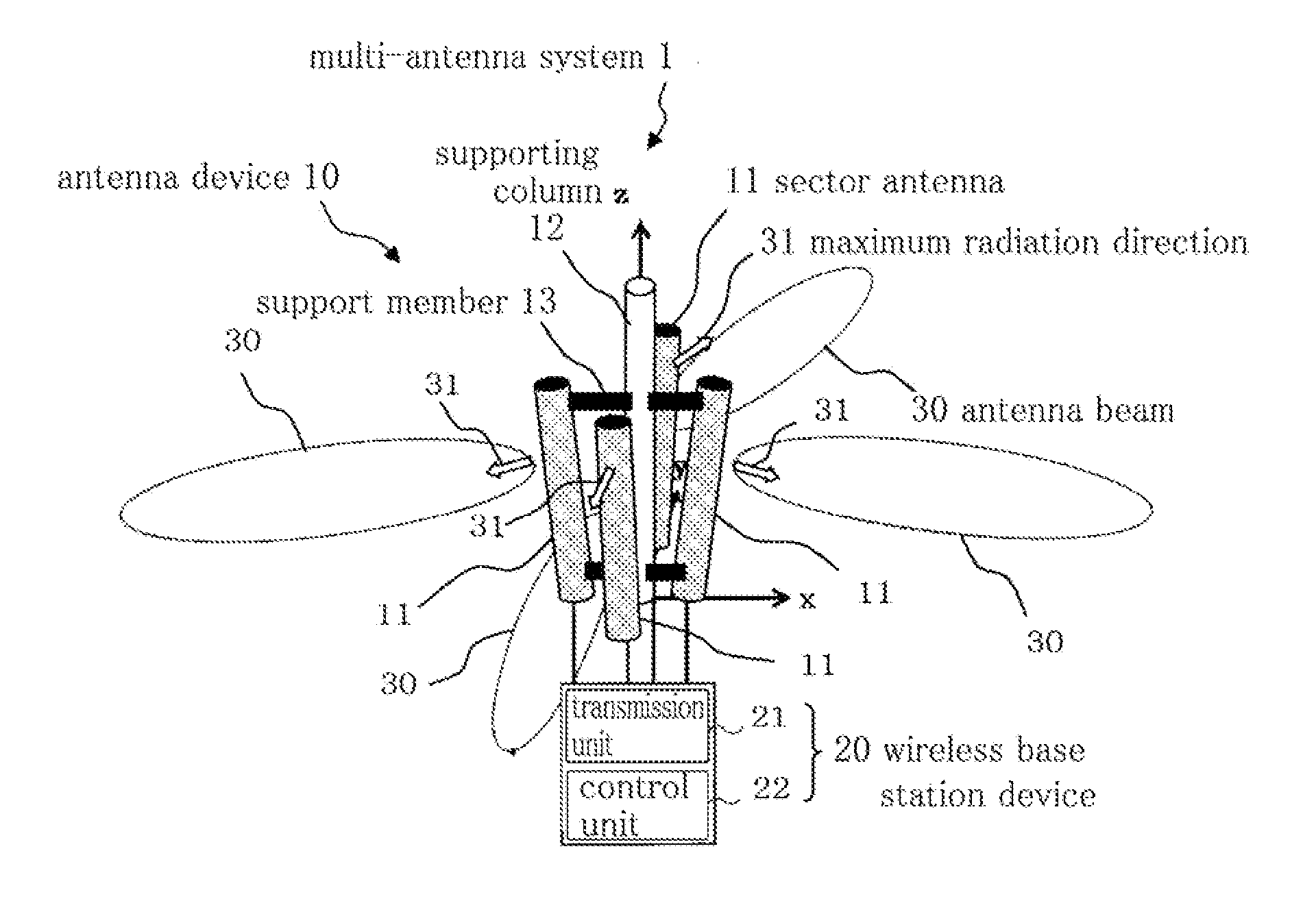
[0025]Hereinafter, a multi-antenna system according to an embodiment of the present invention is described with reference to the drawings. The multi-antenna system according to the present invention can be used in place of a multi-antenna system of an omni-antenna system that performs wireless communication by MIMO.

[0026]FIG. 3 shows a configuration of the multi-antenna system according to the embodiment. The multi-antenna system according to the embodiment includes antenna device 10 and wireless base station device 20 connected to antenna device 10.

[0027]First, antenna device 10 is described. As shown in FIG. 3, antenna device 10 includes four sector antennas 11 for radiating antenna beams 30, supporting column 12 installed in a vertical direction (z-axis direction), and support members 13 projected from supporting column 12 to support sector antennas 11.

[0028]FIG. 4 is a top view showing an arrangement configuration of sector antennas 11. As shown in FIG. 4, four sector antennas 1...


PUM


Abstract

An object of the present invention is to provide an antenna device that exhibits, in wireless communication of an omni-cell system for simultaneously transmitting a plurality of data corresponding to one another, excellent cost performance, and can reduce antenna loss and prevent radio wave interference. This antenna device includes a plurality of sector antennas 11 disposed so that a maximum radial direction where radiation intensity of a radio wave becomes maximum is radially set. The plurality of sector antennas 11 simultaneously transmit a plurality of wireless signals corresponding to one another.

Description

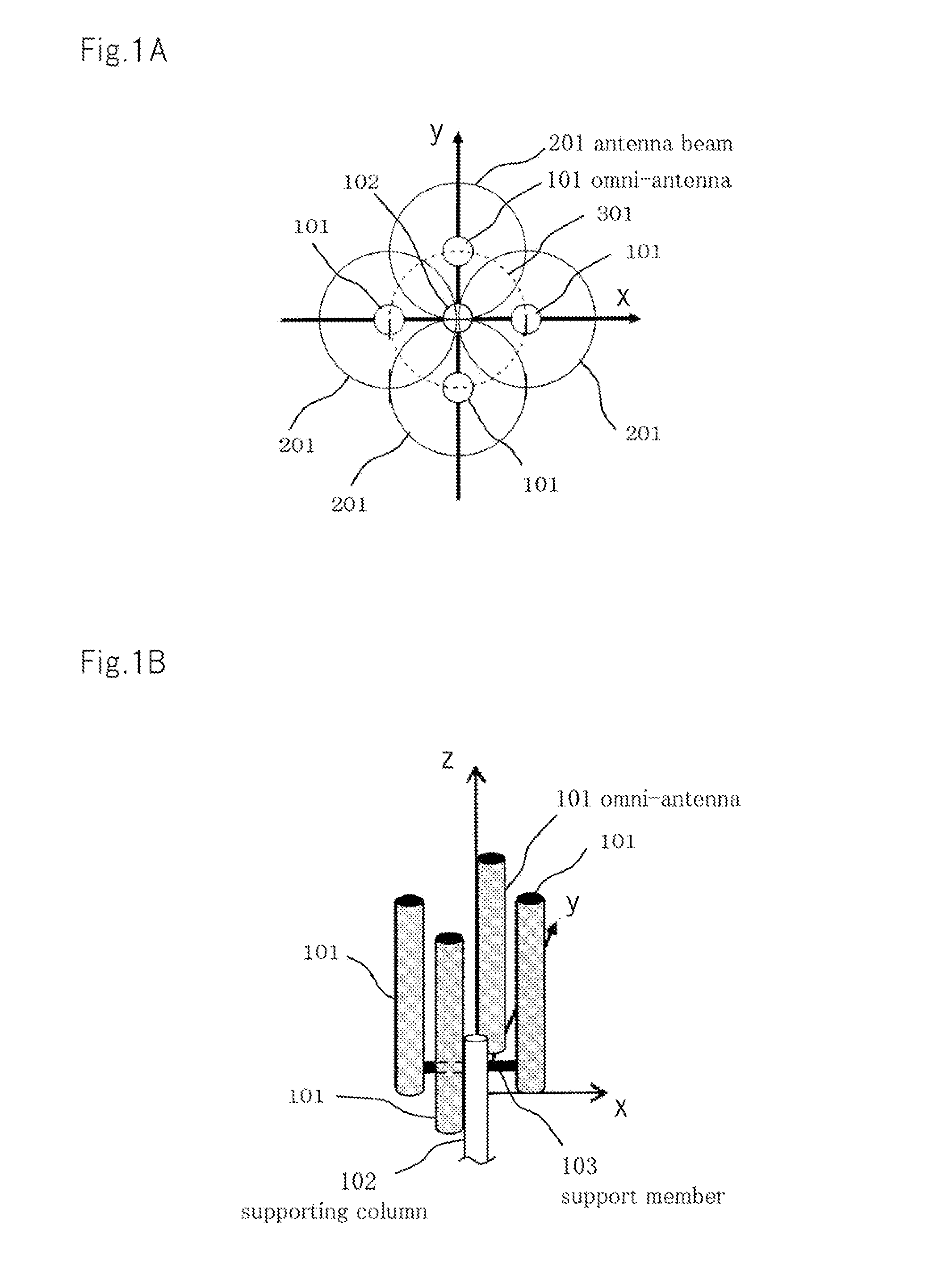
TECHNICAL FIELD[0001]The present invention relates to an antenna device that simultaneously transmits a plurality of wireless signals corresponding to one another from a plurality of antennas, and a multi-antenna system.BACKGROUND ART[0002]For wireless communication, there is a communication system that divides a communication area into a plurality of cells (sections) and locates a base station for each cell. This communication system includes an omini-cell system and a sector cell system. According to the omni-cell system, an omni-antenna that is a nondirectional antenna is installed, and a radio wave is radiated in all directions from this omni-antenna. According to the sector cell system, one cell is divided from a center into a plurality of sector cells, and a sector antenna that is a directional antenna is installed for each sector cell. In other words, the sector cell system enables wireless communication by using one cell for each different sector cell.[0003]In recent years, ...

Claims


Application Information

Patent Timeline
IPC IPC(8): H04L27/26H01Q21/28
CPCH01Q1/246H01Q21/06H01Q25/00H01Q21/20H01Q21/08H01Q21/205
Inventor TANABE, KOSUKE
Owner NEC CORP
Learn More