In-vehicle communications apparatus

a communication apparatus and vehicle technology, applied in the field of vehicle communications equipment, can solve the problems of increased vehicle density, increased communication interference, easy to arise communication interference, etc., to prevent radio wave interference, reduce the amount of communication traffic, and secure the safety of the vehicl

Inactive Publication Date: 2010-08-05
DENSO CORP
View PDF0 Cites 31 Cited by
  • Summary
  • Abstract
  • Description
  • Claims
  • Application Information

AI Technical Summary

Benefits of technology

[0023]A conventional apparatus sets the transmission power (correlated with a communications distance) or transmission cycle to a predetermined fixed value according to a control condition such as a vehicle speed. Thus, compared with the conventional one, the in-vehicle communication apparatus according to the aspect of the present invention can secure the safety in vehicle traveling, and reduce the communications traffic amount of the wireless communications of the whole system, resulting in helping prevent the radio wave interference from arising.

Problems solved by technology

That is, for example, it is better to set up transmission power high in order to realize communications with a distant vehicle; however, if all the vehicles communicate with the fixed high transmission power, the communications interference is apt to easily arise.
In addition, the density of vehicles is often high near intersections or congested areas.
If the same transmission power as that used in the area having the low density of vehicles is used, the communications interference may increase, thereby allowing only the inefficient communications.
As a result, it may be difficult to provide a secured safety at the time of vehicle traveling or to, sufficiently reduce the radio wave interference, thus posing a disadvantage.
As a result, the safety at the traveling of the vehicle cannot be secured enough.
In addition, it is unnecessary to always transmit the information to a long distance even at high speed traveling; further, transmitting always the large electric power at high speed traveling poses the radio wave interference.
In addition, the technology given in Patent document 2 controls the electric power according to relative distance with the communications partner; thus, it is difficult to apply it to the broadcasting type communications, which should have unfixed communications partners.
In this regard, however, when the use for the safety is considered, it is unnecessary to transmit the information to the vehicle in a long distance in high repetition times; thus, unnecessary radio wave interference may be generated.

Method used


Image

  • In-vehicle communications apparatus
  • In-vehicle communications apparatus
  • In-vehicle communications apparatus

Examples


first embodiment

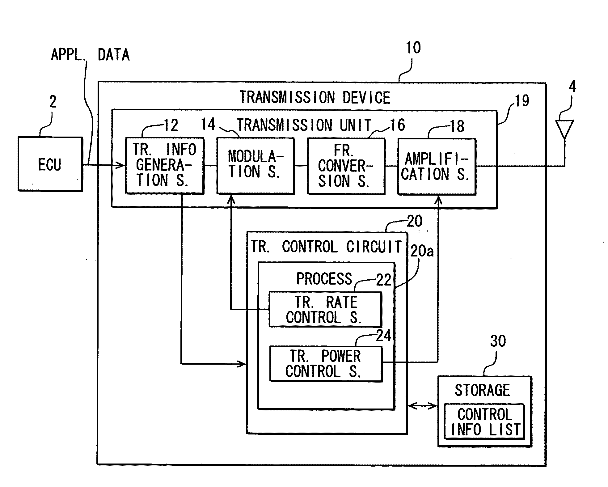
[0051]FIG. 1 is a block diagram illustrating a configuration of a transmission device 10 of an in-vehicle communications apparatus, which is mounted in a subject vehicle, of a first embodiment according to the present invention.

[0052]As illustrated in FIG. 1, the transmission device 10 includes the following: a transmission information generation section 12 to acquire application data as transmit data (i.e., transmission data) from at least one (single or several) electronic control section (ECU) 2 which is mounted in the subject vehicle, and to generate packet data (transmission packet) for transmission or communications; a modulation section 14 to transform the transmission packet, which is generated in the transmission information generation section 12, into a transmission signal according to a predetermined transmission rate; a frequency conversion section 16 to perform a frequency conversion from the transmission signal outputted by the modulation section 14 to a high-frequency...

second embodiment

[0098]Next, FIG. 9 is a block diagram illustrating a configuration of an in-vehicle communications apparatus mounted in a subject vehicle, according to a second embodiment of the present invention.

[0099]The in-vehicle communications apparatus of the present second embodiment has almost the same configuration as that of the in-vehicle communications apparatus of the first embodiment illustrated in FIG. 1. The different point from the first embodiment is in that the second embodiment includes a subject vehicle information detection section 60 to detect a travel speed and present position of the subject vehicle. For instance, the subject vehicle information detection section 60 includes a GPS (Global Positioning System) receiver.

[0100]In the second embodiment, a transmission control circuit 20 executes almost the same operation as that in the first embodiment. The detailed explanation about common portions is thus omitted in the following explanation; the different portions are only ex...

third embodiment

[0125]Next, FIG. 18 is a block diagram illustrating a configuration of an in-vehicle communications apparatus according to a third embodiment of the present invention.

[0126]The in-vehicle communications apparatus of the present embodiment has almost the same configuration as that of the in-vehicle communications apparatus of the third modification of the first embodiment illustrated in FIG. 8. The different point is in that the present third embodiment further includes a subject vehicle information detection section 60 for detecting a travel speed and present position of the subject vehicle, and an other vehicle information detection section 70.

[0127]The other vehicle information detection section 70 is to extract other vehicle information for indicating a travel speed and present position of another vehicle out of transmission data (application data) from peripheral vehicles. Such transmission data are demodulated by the demodulation section 56 of the reception unit 50.

[0128]Furthe...


PUM


Abstract

Application data generated by an ECU is wireless transmitted by a transmission device in a subject vehicle so as to periodically change a communications distance by changing, every transmission timing, at least one of (i) a transmission rate, which is used in transforming a transmission packet into a transmission signal in a modulation section, and (ii) a transmission power, which is configured by an amplification section to amplify the transmission signal. As a result, the data transmission from the subject vehicle can be made (i) in high repetition times with respect to a nearby vehicle having a greater risk of collision (i.e., time to collision being shorter), and (ii) in low repetition times with respect to a distant vehicle having a less risk of collision (i.e., time to collision being longer).

Description

CROSS REFERENCE TO RELATED APPLICATION[0001]The present application is based on and incorporates herein by reference Japanese Patent Application No. 2009-22804 filed on Feb. 3, 2009.FIELD OF THE INVENTION[0002]The present invention relates to an in-vehicle communications apparatus used for a wireless communication system in which several communications terminals execute broadcast type data transmission via a common wireless channel.BACKGROUND OF THE INVENTION[0003][Patent document 1] JP-2004-343467 A[0004][Patent document 2] JP-2007-6395 A[0005][Patent document 3] JP-2008-227797 A[0006][Non-patent Document 1] Advanced Safety Vehicle (ASV) Promotion Planning Report, Regarding activity results in 3rd term ASV plan, (March, 2006 (Heisei 18)) The Ministry of Land, Infrastructure and Transport Road Transport Bureau, Advanced Safety Vehicle Promotion Investigative Commission, Page 75[0007]In recent years, there is developed a wireless communications system in which inter-vehicle (vehicle-...

Claims


Application Information

Patent Timeline
Patent Type & Authority Applications(United States)
IPC IPC(8): G06F19/00G08G1/09H04W4/04H04W4/06H04W28/18H04W52/18
CPCH04W52/267
Inventor KOSAI, JUNMATSUGATANI, KAZUOKIKATO, SHUGOSAITO, TOSHIYA
Owner DENSO CORP
Why Eureka
Try Eureka