Backlight module and liquid crystal display

Inactive Publication Date: 2010-04-29
CORETRONIC
View PDF4 Cites 7 Cited by
  • Summary
  • Abstract
  • Description
  • Claims
  • Application Information

AI Technical Summary

Benefits of technology

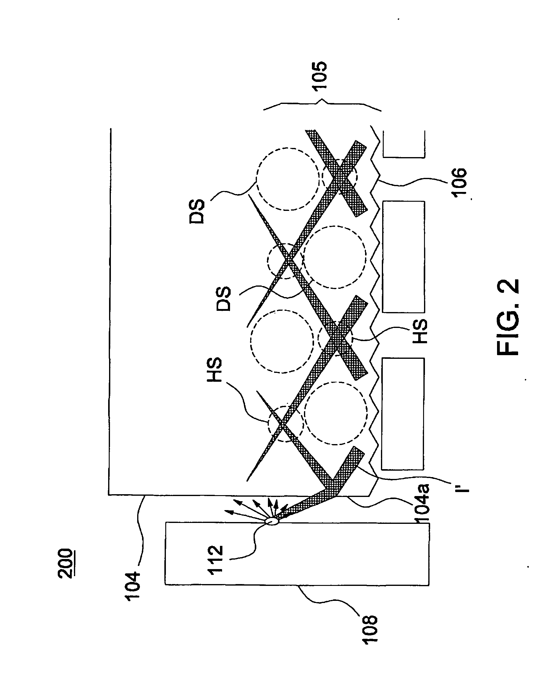
[0006]The present invention is directed to a backlight module and a liquid crystal display, capable of avo

Problems solved by technology

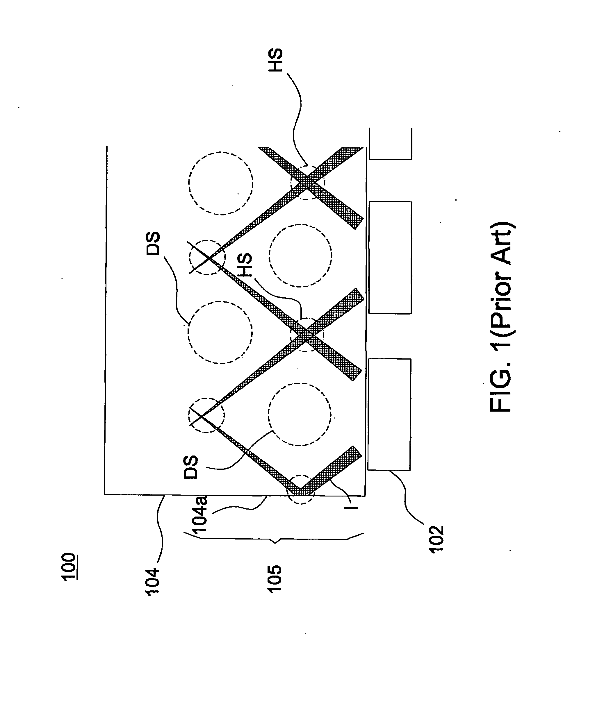
Therefore, there is a need to reserve a large light mixing region 105 for uniformly diffusing the light ener

Method used


Image

  • Backlight module and liquid crystal display
  • Backlight module and liquid crystal display
  • Backlight module and liquid crystal display

Examples


Embodiment Construction

[0021]In the following detailed description of the preferred embodiments, reference is made to the accompanying drawings which form a part hereof, and in which are shown by way of illustration specific embodiments in which the invention may be practiced. In this regard, directional terminology, such as “top,”“bottom,”“front,”“back,” etc., is used with reference to the orientation of the Figure(s) being described. The components of the present invention can be positioned in a number of different orientations. As such, the directional terminology is used for purposes of illustration and is in no way limiting. On the other hand, the drawings are only schematic and the sizes of components may be exaggerated for clarity. It is to be understood that other embodiments may be utilized and structural changes may be made without departing from the scope of the present invention. Also, it is to be understood that the phraseology and terminology used herein are for the purpose of description an...


PUM


Abstract

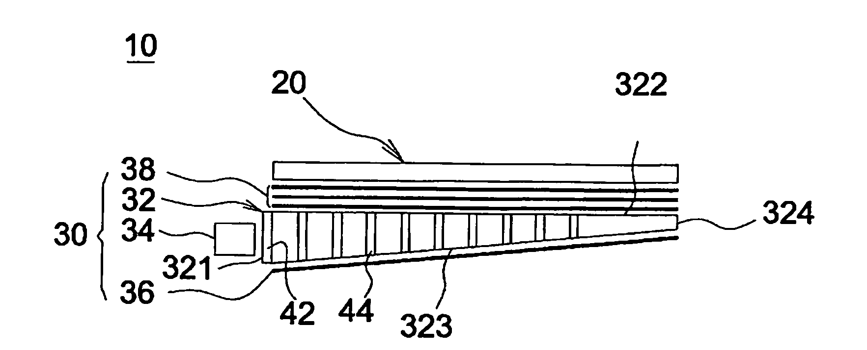
A backlight module includes at least one point light source and a light guide plate. The light guide plate includes a light emitting surface, a bottom surface, a light incident surface, a first side surface, a second side surface, a first microstructure, and a second microstructure. The bottom surface is opposite to the light emitting surface, the light incident surface connects the light emitting surface and the bottom surface, the point light source is disposed adjacent to the light incident surface, and the first microstructure is formed on the light incident surface. The first side surface is opposite to the light incident surface and connects the light emitting surface and the bottom surface, and the second side surface connects the light emitting surface, the bottom surface, the light incident surface, and the first side surface. The second microstructure is formed on the second side surface.

Description

CROSS-REFERENCE TO RELATED APPLICATION[0001]This application claims the priority benefit of Taiwan application serial no. 97141125, filed on Oct. 27, 2008. The entirety of the above-mentioned patent application is hereby incorporated by reference herein and made a part of this specification.BACKGROUND OF THE INVENTION[0002]1. Field of the Invention[0003]The present invention relates to a backlight module and a liquid crystal display including the backlight module.[0004]2. Description of Prior Art[0005]FIG. 1 is a schematic view of a conventional backlight module 100 using a point light source as a side light source. Referring to FIG. 1, when the point light source 102 (for example a light emitting diode) is used as the side light source, the front end of the light guide plate 104 may generate a hot spot HS and a dark spot DS distributed alternately base on the light emitting characteristic of the point light source 102. Therefore, there is a need to reserve a large light mixing regi...

Claims


Application Information

Patent Timeline
IPC IPC(8): G02F1/1335F21V7/04
CPCG02B6/0035G02B6/0016
Inventor KUO, HAO-JANLIU, MING-DAH
Owner CORETRONIC
Why Eureka
Try Eureka