Transfer film, method of manufacturing the same, transfer method and object surface structure

a technology of transfer film and surface structure, which is applied in the directions of transportation and packaging, printing, and thermal transfer technology, etc., can solve the problems of increasing labor cost and fabrication time, prone to damage of the ink layer, and the development of thermal transfer technology

Inactive Publication Date: 2010-04-29
COMPAL ELECTRONICS INC
View PDF3 Cites 79 Cited by
  • Summary
  • Abstract
  • Description
  • Claims
  • Application Information

AI Technical Summary

Benefits of technology

[0046]In order to make the aforementioned and other features and advantages of the present inven...

Problems solved by technology

After the thermal transfer, since the ink layer thermally transferred on the products directly contacts with the external environment, the ink layer is prone to be damaged, e.g. scratched.
The step of manually spray-coating the protection layer, however, raises the labor cost and...

Method used


Image

  • Transfer film, method of manufacturing the same, transfer method and object surface structure
  • Transfer film, method of manufacturing the same, transfer method and object surface structure
  • Transfer film, method of manufacturing the same, transfer method and object surface structure

Examples


example i

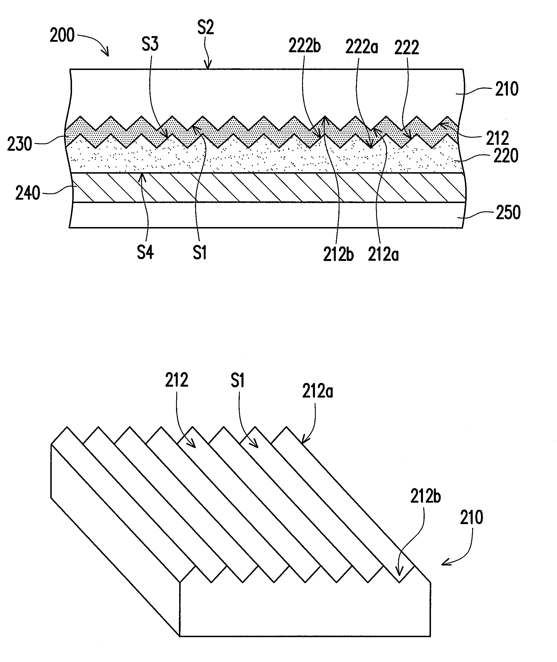
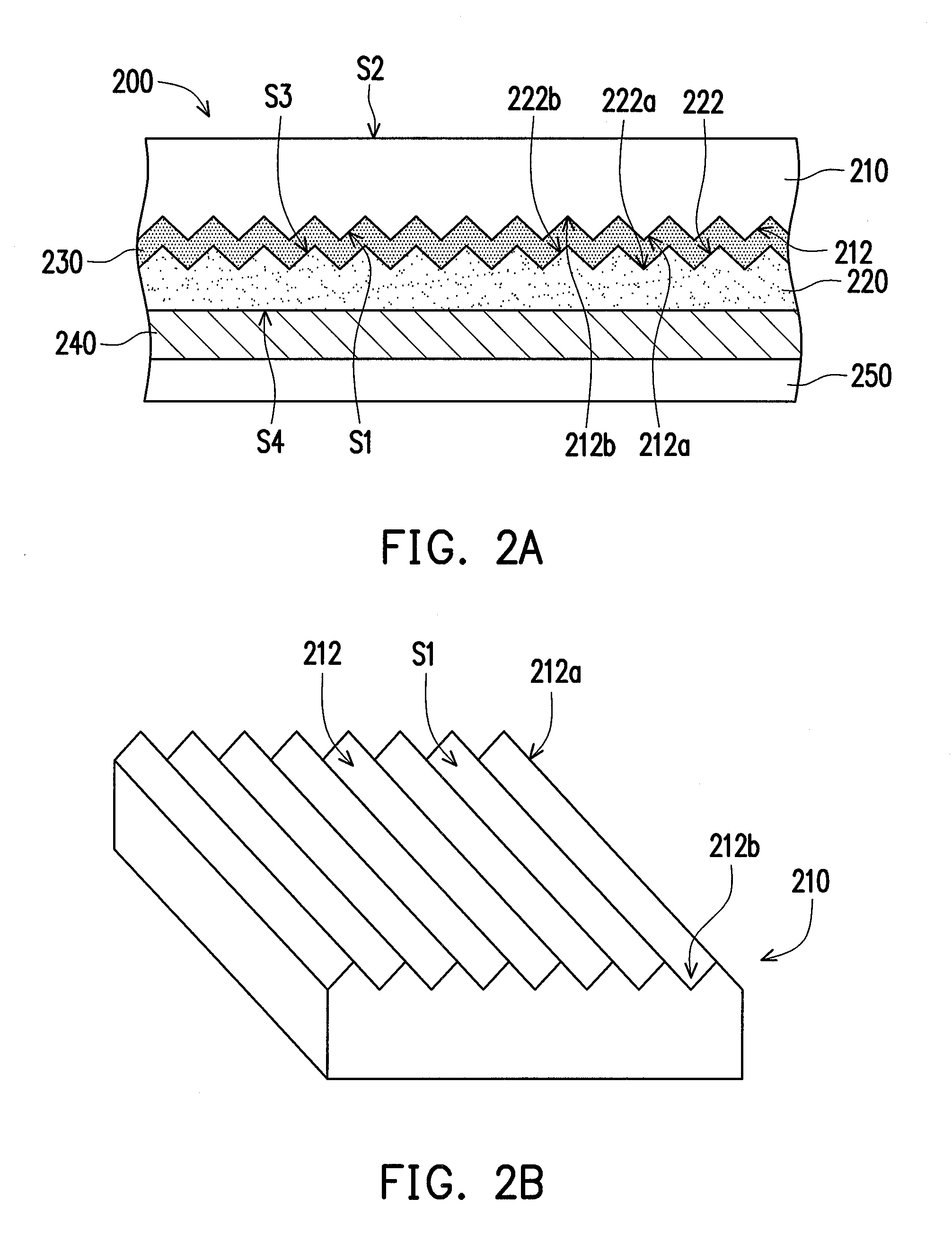
[0090]A submount is provided, which is a polyester film with a thickness of 50 μm. A brushed filament texture with jog structure is fabricated on the submount using a roller with rough surface, so as to form a substrate with the brushed filament texture. A thermosetting acrylic release resin is then coated on the substrate with the brushed filament texture, and serves as a release layer. Afterwards, a liquid radiation curing resin layer is coated on the release layer by means of the scraper coating. The composition proportion of the aforesaid liquid radiation curing resin layer includes 60˜120 units of bifunctional acrylate-based monomer, 60˜120 units of bifunctional epoxy acrylate-based oligomer, 5˜10 units of photoinitiator, and 50˜100 units of ethyl acetate solvent.

[0091]Thereafter, the liquid resin layer is baked by a hot-air oven of 100° C. and then radiated by ultraviolet (UV) with energy of 800 mJ / cm2, so as to cure the liquid resin layer and thus form a protection layer with...

example ii

[0093]A finished product is fabricated in a similar manner of the process illustrated in Example I, while the difference lies in that the composition proportion of the liquid resin layer is changed to 40˜80 units of bifunctional acrylate-based monomer, 20˜60 units of multiple functional acrylate-based monomer, 60˜120 units of bifunctional polyurethane acrylate-based oligomer, 5˜10 units of photoinitiator, and 50˜100 units of ethyl acetate solvent.

[0094]The surface hardness, chemical resistance and abrasion resistance of the finished products obtained from said Examples I and II are evaluated under testing standards described as follows.

[Surface Hardness Test]

[0095]A pencil hardness tester under a load of 500 g is utilized for testing, wherein Mitsubishi pencils special for hardness test are adopted. The pencil was moved at an angle of 45° on the surface of the completely cured protection layer so as to test progressively from hard to soft in accordance with hardness order of the pen...

example iii

[0100]A submount is provided, which is a polyester film with a thickness of 50 μm. A desired three-dimensional pattern is printed directly on the submount, so as to form a substrate with the three-dimensional pattern. A thermosetting acrylic release resin is then coated on the three-dimensional pattern, and serves as a release layer. Afterwards, a liquid radiation curing resin layer is coated on the release layer by means of the scraper coating. The composition proportion of the aforesaid liquid radiation curing resin layer includes 60˜120 units of bifunctional acrylate-based monomer, 60˜120 units of bifunctional epoxy acrylate-based oligomer, 5˜10 units of photoinitiator, and 50˜100 units of ethyl acetate solvent.

[0101]Thereafter, the liquid resin layer is baked by a hot-air oven of 100° C. and then radiated by ultraviolet (UV) with energy of 800 mJ / cm2, so as to cure the liquid resin layer and thus form a protection layer with a thickness of 8 μm. An ink layer is then printing on ...


PUM

PropertyMeasurementUnit
Adhesivityaaaaaaaaaa
Metallic bondaaaaaaaaaa
Surface structureaaaaaaaaaa

Abstract

A transfer film including a protection layer and a substrate is provided. The substrate has a first surface with a first three-dimensional pattern and a second surface. The first three-dimensional pattern has at least one protrusion portion or at least one recess portion. The protection layer is disposed on the substrate and has a third surface and a fourth surface. The third surface contacts the first surface and has a second three-dimensional pattern complementary to the first three-dimensional pattern. The second three-dimensional pattern of the third surface is formed by covering the first three-dimensional pattern of the first surface. The protection layer and the substrate are separated after transfer, so as to expose the second three-dimensional pattern.

Description

CROSS-REFERENCE TO RELATED APPLICATION[0001]This application claims the priority benefit of U.S. provisional application Ser. No. 61 / 108,012, filed on Oct. 23, 2008. The entirety of the above-mentioned patent application is hereby incorporated by reference herein and made a part of this specification.BACKGROUND[0002]1. Technical Field[0003]The present invention generally relates to a transfer film, a method of manufacturing the same, a transfer method and a three-dimensional (3D) structure. More particularly, the present invention relates to a transfer film having a substrate with a three-dimensional pattern, a method of manufacturing the same, a transfer method and a three-dimensional structure.[0004]2. Description of Related Art[0005]Nowadays, thermal transfer technology is widely applied to fabrication process of goods, such as patterns or labels. Thermal transfer film is frequently utilized in the thermal transfer technology so as to thermal transfer an ink layer on a surface of...

Claims


Application Information

Patent Timeline
IPC IPC(8): B41M5/40B44C1/17
CPCB44C1/17Y10T428/2804Y10T428/2848Y10T428/24364Y10T428/24537Y10T428/2839Y10T428/24521Y10T428/2457Y10T428/24562Y10T428/24843Y10T428/28B41B3/00
Inventor CHIU, JU-CHENCHEN, YIN TA
Owner COMPAL ELECTRONICS INC
Why Eureka
Try Eureka