Tool for the connection of tubes by means of connection sleeves

a technology for connecting sleeves and tools, applied in the direction of forging hammers, mechanical equipment, pumps, etc., can solve the problems of increasing work times and operating difficulties, limiting the maximum number of punches which can be mounted on the tool, and the ineffective use of fixed operating machines. the effect of cost limitation

Active Publication Date: 2010-05-06
AUTOCONDIZIONATORI ZANI
View PDF27 Cites 11 Cited by
  • Summary
  • Abstract
  • Description
  • Claims
  • Application Information

AI Technical Summary

Benefits of technology

[0031]A second object of the present invention is that of making available a device for the actuation of work tools, for example clinching tools, which permits overcoming the mentioned drawbacks of the currently employed tools.
[0032]Further object of the invention is that of achieving said objectives in the context of simple, rational solutions with limited costs.

Problems solved by technology

In the repairing of conveying ducts, such fixed operating machines cannot be effectively used since they do not permit operating directly on the conveying duct without removing it from the system.
For this reason, the connection sleeve must necessarily be axially inserted inside said encircling structure; this requires that the conveying duct is removed beforehand from the related system, considerably increasing the work times and the operating difficulties.
This fact, in addition to leading to the realisation of imperfect circumferential crimps, also limits the maximum number of punches which can be mounted on the tool, beyond which the more tilted punches would result totally ineffective.
For the known tools, such maximum limit is six punches, and is therefore generally insufficient for ensuring the watertight seal of the connection which is made between the connection sleeve and the rubber tube inserted in it.
Therefore, one particularly noted drawback of the known work tools lies in the fact that their use is generally very slow and tiring for the operator.

Method used


Image

  • Tool for the connection of tubes by means of connection sleeves
  • Tool for the connection of tubes by means of connection sleeves
  • Tool for the connection of tubes by means of connection sleeves

Examples


Embodiment Construction

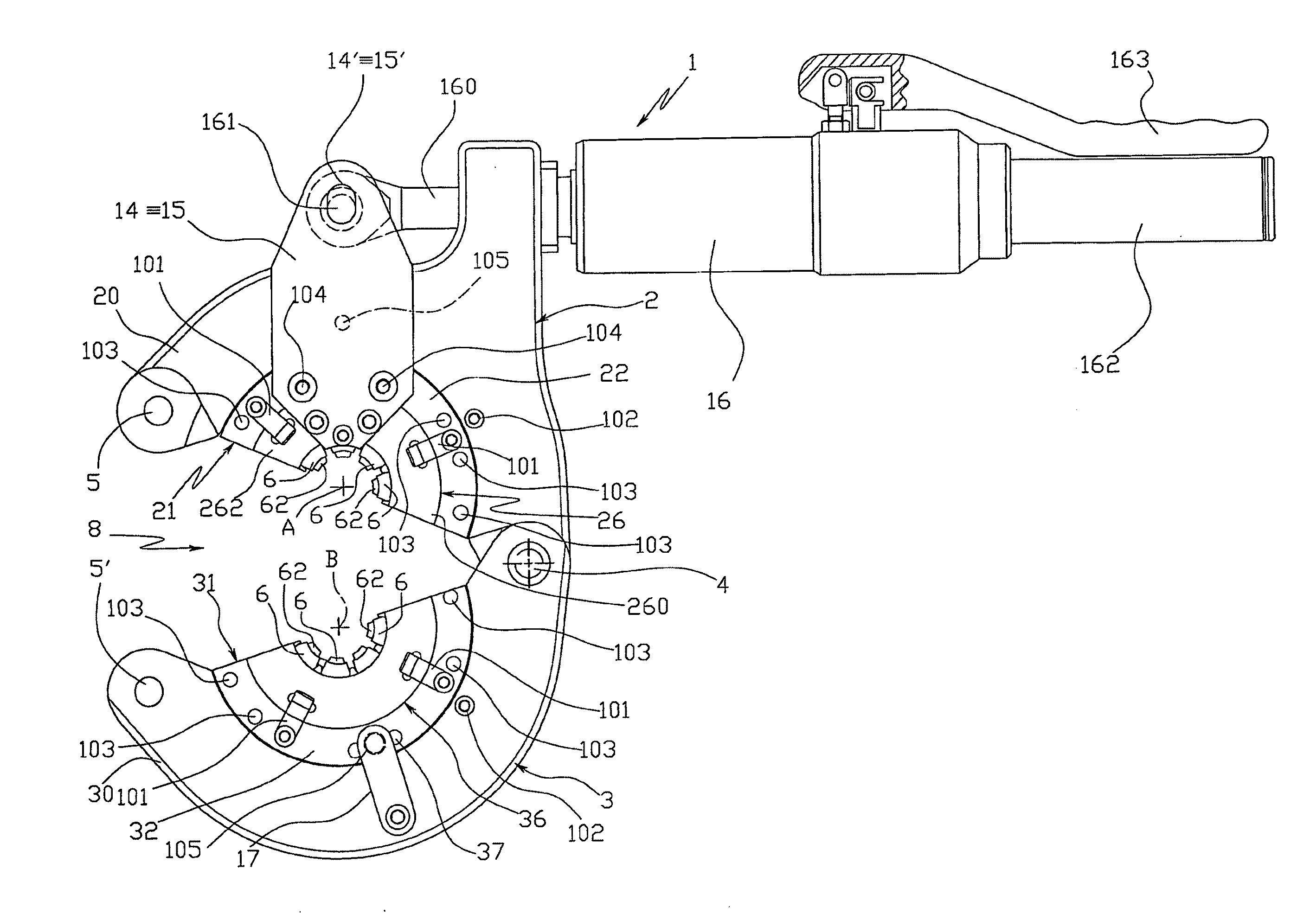
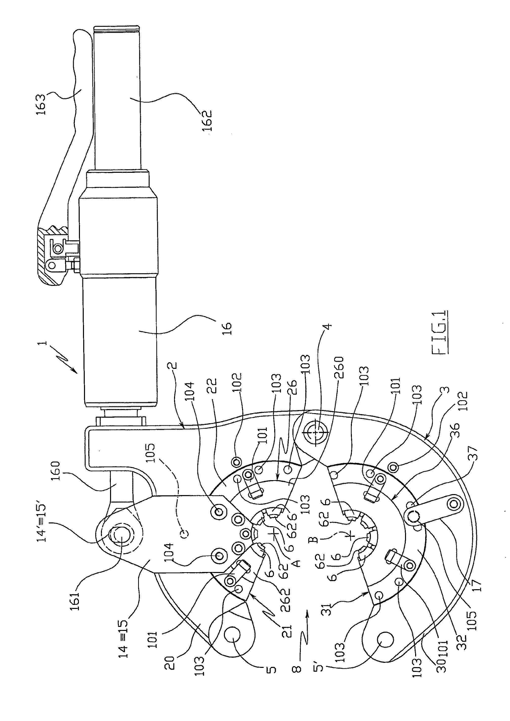
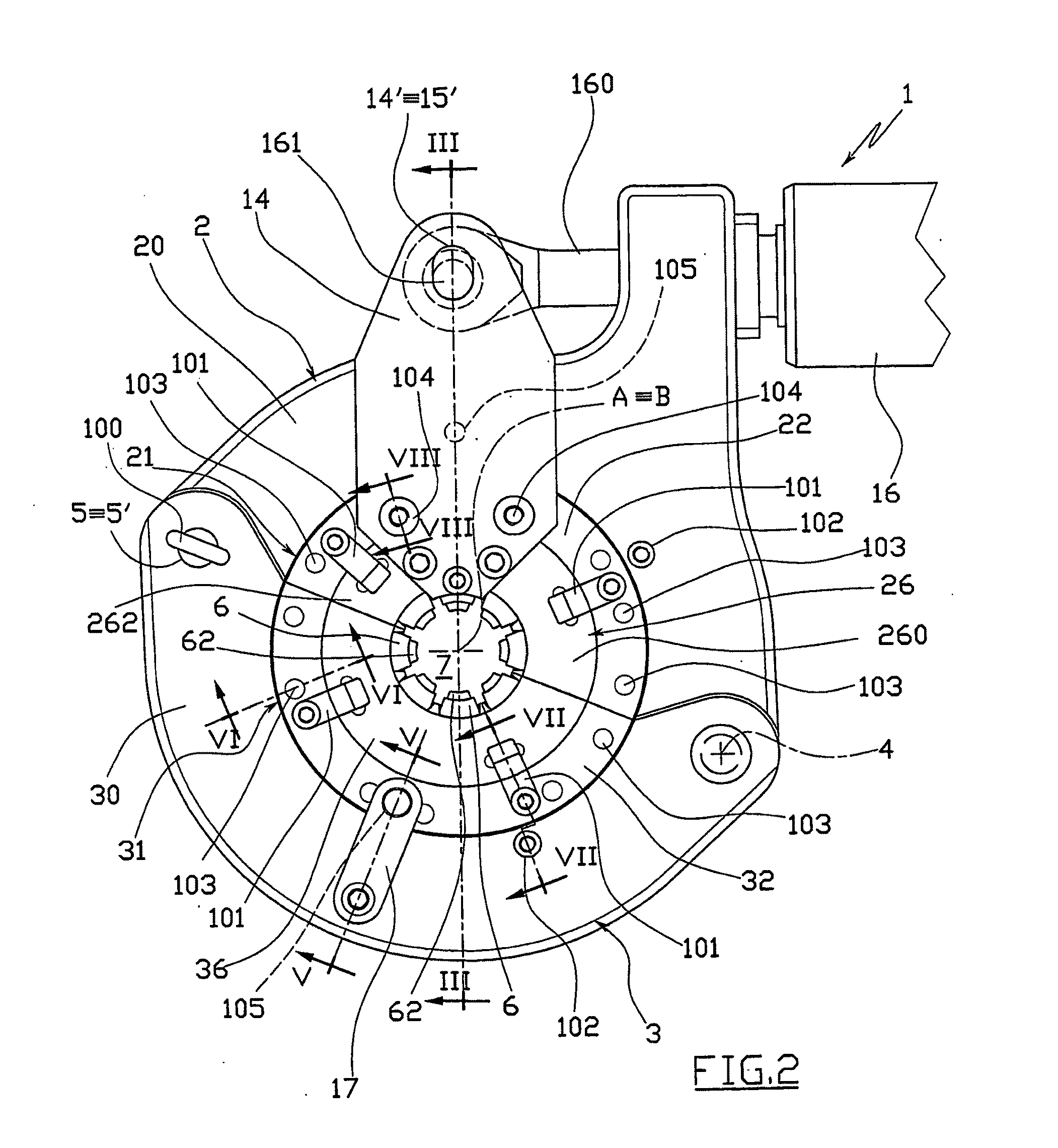
[0058]FIGS. 1-9 illustrate a portable clinching tool 1 which serves to connect rubber tubes T, typically for fluids under pressure, by means of appropriate connection elements G, of the type of that shown in FIG. 10, i.e. comprising an intermediate tube I and two generally metallic connection sleeves C, within which the ends of the rubber tubes T to be connected are inserted.

[0059]In particular, the tool 1 is adapted to plastically deform each connection sleeve C to make a series of circumferential crimps P on it, which, pressed against the respective rubber tube T, fix the sleeve to the tube.

[0060]As shown in FIGS. 1 and 2, the tool 1 comprises a fixed jaw 2 and a movable jaw 3, which are mutually connected by means of a kinematic system which permits them to be mutually moved between an open rest position and a closed work position.

[0061]Each of said jaws, 2 and 3, comprise a lunette-shaped outer body, 20 and 30, whose concavity houses an activated inner band 21 and 31, substantia...


PUM

PropertyMeasurementUnit
pressureaaaaaaaaaa
plastic deformationaaaaaaaaaa
sizeaaaaaaaaaa

Abstract

A tool for the connection of tubes (T) by means of connection sleeves (C), comprising two jaws (2, 3) which are mutually movable between an open rest position, and a closed work position wherein they define an annular reception seat (7) of the connection sleeve (C), and wherein they turn a circumferential series of radial punches (6) towards the sleeve (C); said jaws (2, 3) each comprising at least one punch (6) sliding towards the centre of said reception seat (7), and being mutually connected by means of a kinematic system which permits them, when they are found in said open rest position, to confer a generally open-ring shape to said reception seat (7), through whose lateral opening (8) the connection sleeve (C) can be inserted and extracted by lateral movement.

Description

TECHNICAL FIELD[0001]The present invention refers to a tool for the connection of tubes by means of connection sleeves in plastically deformable, typically metallic material.[0002]More in particular, the present invention refers to a tool for the connection of tubes for fluids under pressure, intended for example for making the conveying ducts of the refrigerating fluid in the conditioning systems of motor vehicles.BACKGROUND ART[0003]As is known, said conveying ducts are generally situated inside the engine compartment of the motor vehicles, where they extend in a winding progression so to not interfere with the other devices contained therein.[0004]For this reason, the conveying ducts are generally composed of a succession of substantially rectilinear rubber tubes, which are connected with each other, watertight, by means of appropriate connection elements made of typically metallic, plastically deformable material which can be bent to make the elbows of the duct.[0005]Said connec...

Claims


Application Information

Patent Timeline
Patent Type & Authority Applications(United States)
IPC IPC(8): B25B27/14B21D39/04
CPCB21D39/048B25B27/146F04B17/00F04B23/02Y10T29/5367Y10T29/53657Y10T29/53987Y10T29/53678Y10T29/5383
Inventor VERNASCA, IVALDOVERNASCA, CARLOVERNASCA, FRANCESCO
Owner AUTOCONDIZIONATORI ZANI
Why Eureka
Try Eureka