Eureka AIR delivers breakthrough ideas for toughest innovation challenges, trusted by R&D personnel around the world.

Provision for rapid warming of steam piping of a power plant

a technology for power plants and steam pipes, applied in the direction of machines/engines, liquid degasification, separation processes, etc., can solve the problems of reducing the overall efficiency of the power plant, and the time required for steam to reach the required minimum conditions at the mscv inlet is relatively long

Inactive Publication Date: 2010-05-06
GENERAL ELECTRIC CO
View PDF7 Cites 13 Cited by
  • Summary
  • Abstract
  • Description
  • Claims
  • Application Information

AI Technical Summary

Benefits of technology

"The invention provides a steam power plant and a method of operating it that includes a main steam control valve, a bypass line, an evacuator line, and a warming line. The method involves removing a portion of the steam from the piping upstream of the main steam control valve and disposing it into the evacuator line when a characteristic of the steam satisfies a threshold. The evacuator line then removes the steam from the flowpath conduit and sends it to a condenser. The warming line, which is connected to the evacuator line, removes an additional portion of the steam from the flowpath conduit and sends it to the steam turbine. This allows for better control of the steam temperature and ensures efficient power generation."

Problems solved by technology

With this configuration, the time required for the steam to reach the required minimum conditions at the MSCV inlet is relatively long due to improper warming and / or draining of steam pipeline.
As a result, the overall efficiency of the power plant may be decreased.

Method used


Image

  • Provision for rapid warming of steam piping of a power plant
  • Provision for rapid warming of steam piping of a power plant

Examples


Embodiment Construction

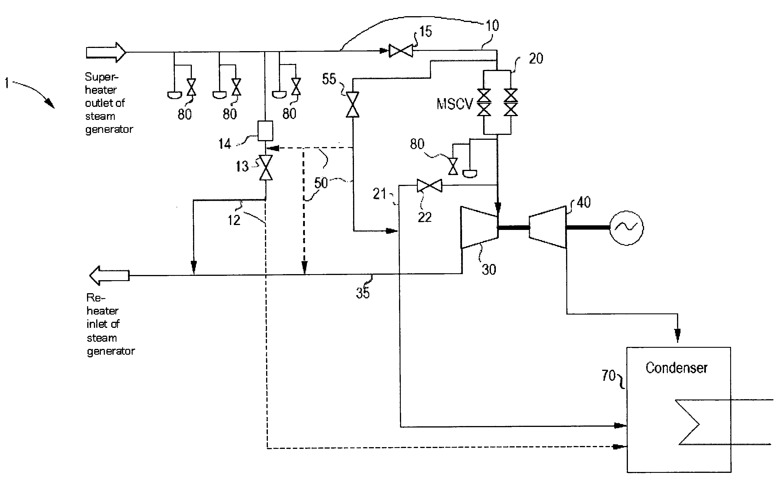
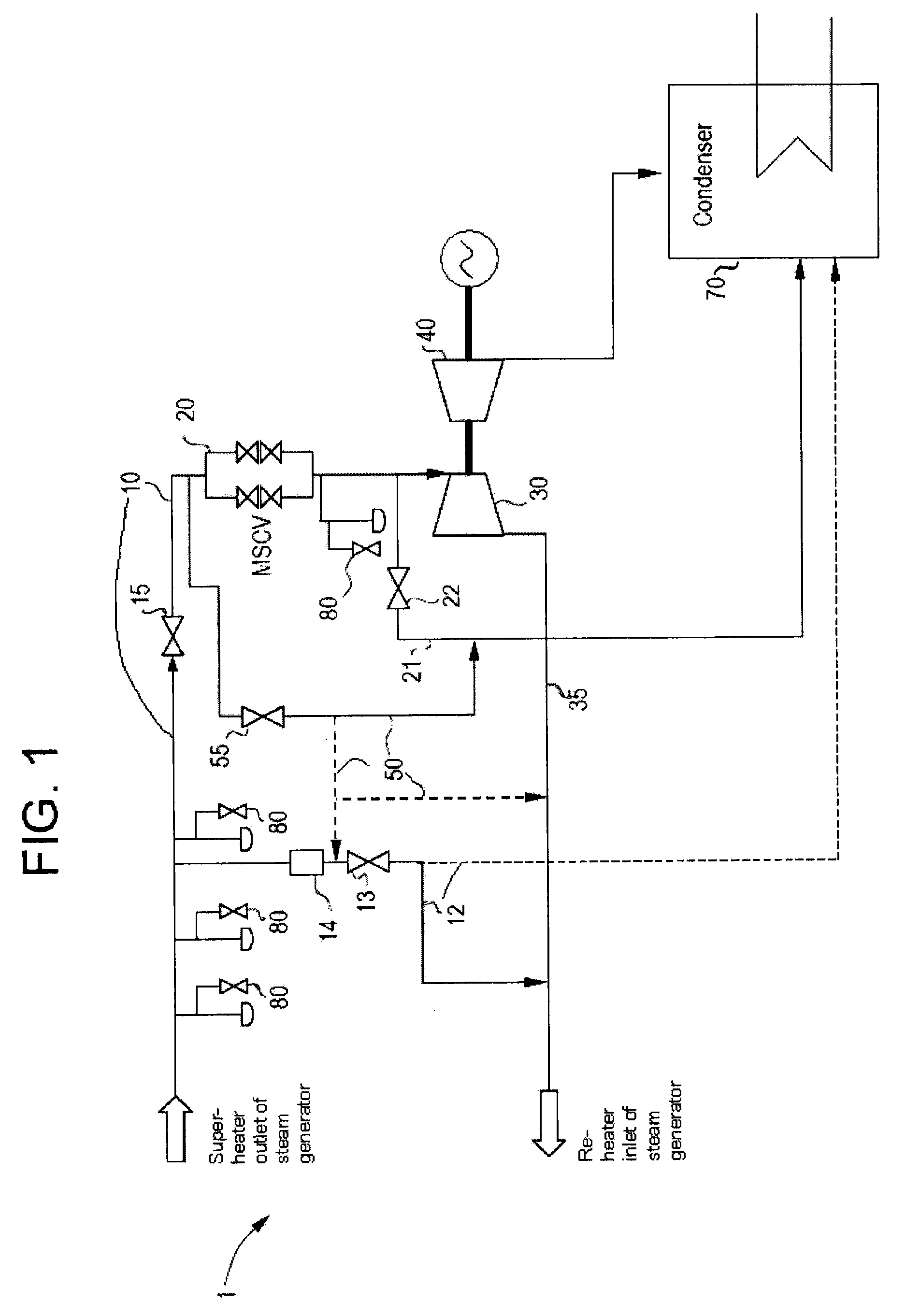
[0010]With reference to FIG. 1, a steam power plant 1 is provided which includes a flowpath conduit, such as a steam pipeline 10, to couple the heat generator and the high pressure steam turbine (HPST) 30 with one another, and a main steam control valve (MSCV) 20, disposed along the piping upstream of the HPST 30, to admit the steam to the HPST 30 when a characteristic thereof satisfies a threshold.

[0011]During the start up of the steam power plant 1, steam cannot be admitted to the HPST 30 unless the steam has a certain minimum temperature and / or a certain minimum pressure based on the operational specifications of the HPST 30 Upon a start up of the power plant 1, depending on the state of the plant before start up, the temperature and pressure of the steam generated by the steam generator will not meet the certain minimums upstream of the MSCV 20 due to improper warming and draining of steam pipeline 10.

[0012]To insure that the MSCV 20 does not open until the minimum condition(s) ...


PUM

PropertyMeasurementUnit
thresholdaaaaaaaaaa
thermal environmentaaaaaaaaaa
pressureaaaaaaaaaa

Abstract

A steam power plant, in which steam from a steam generator is received by a steam turbine, is provided and includes a conduit, a main steam control valve (MSCV) disposed along the conduit to admit the steam to the steam turbine when a characteristic thereof satisfies a threshold, a bypass line, coupled to the conduit between a super-heater and a valve, including a bypass line valve which is opened until the threshold is satisfied such that the bypass line removes a portion of the steam, an evacuator line, coupled to the conduit between the MSCV and the steam turbine, including an evacuator valve which is opened to regulate a thermal environment within the steam turbine during a start up thereof, and a warming line originating between the valve and the MSCV on the conduit and terminating downstream of the evacuator valve disposed along the evacuator line.

Description

BACKGROUND OF THE INVENTION[0001]In general, a steam power plant includes a heat source, a steam generator by which steam is generated at multiple pressure levels and heated to a desired superheated level by the heat of the heat source and a system, such as a steam turbine, in which the steam is used for power generation by expansion in the steam turbine.[0002]In such a power plant, steam produced in this manner is transmitted along steam pipelines to the steam turbine. Typically, just upstream of the steam turbine is a main steam control valve (MSCV) located in the steam pipeline. During startup of the steam turbine, the MSCV is kept in a closed condition until the steam in the steam pipeline reaches certain minimum conditions (i.e., minimum temperatures and / or pressures).[0003]Once the minimum conditions are reached, the MSCV is opened and a portion of the steam is permitted to enter the high pressure steam turbine (HPST) where the steam is employed for power generation. The porti...

Claims


Application Information

Patent Timeline
Patent Type & Authority Applications(United States)
IPC IPC(8): F01K9/00F01K13/00
CPCF01K13/02
Inventor PANCHATSARAM, THILEEPANBASHA, ASLAM
Owner GENERAL ELECTRIC CO
Why Eureka
Eureka Blog
Learn More