Connector apparatus and system for explosion proof engine

a technology of connectors and connector devices, applied in the direction of cable inlet sealing means, multi-purpose tools, charge feed systems, etc., can solve the problems of extending the connection between points (terminals, components), generating sparks, flames and/or intensely hot fumes, etc., and achieves the effect of convenient assembly and disassembly

Active Publication Date: 2010-05-06
MIRETTI SPA
View PDF14 Cites 62 Cited by
  • Summary
  • Abstract
  • Description
  • Claims
  • Application Information

AI Technical Summary

Benefits of technology

[0014]In accordance with another aspect of the invention, selected sensors may be individually packaged, potted and encased in an explosion proof enclosure whereby the sensors can be eliminated as a source of generating a hazardous condition (e.g., sparking). The sensors may be packaged to have a threaded termination or to be slip fitted (non threaded). The encapsulated sensors may be coupled to terminals within an explosion proof enclosure via the feed through connectors discussed above.
[0015]The explos

Problems solved by technology

A potential source of sparks is circuitry and machinery used to perform certain desired operations.
For example, an internal combustion engine (ICE) and its associated circuits (e.g., motors) normally generate sparks, flames and/or intensely hot fumes during their operation (i.e., a hazardous condition).
A problem exists in extending connections between points (terminals, components) inside the explosion proof compartment and points (terminals, components) outside the compartment.
However, known feed through connectors are difficult to assemble and do not ensure that hazardous condition(s), e.g., sparks, emanating from the explosion proof compartment is/are inhibited from passing through the connector.
Another problem arises out of the use of numerous di

Method used


Image

  • Connector apparatus and system for explosion proof engine
  • Connector apparatus and system for explosion proof engine
  • Connector apparatus and system for explosion proof engine

Examples


Embodiment Construction

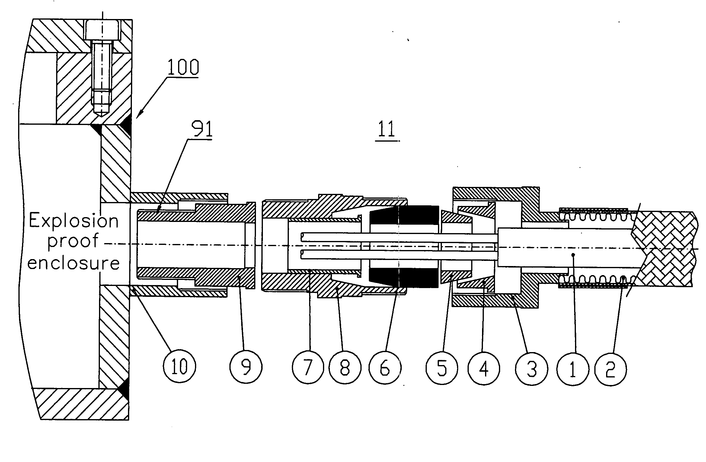
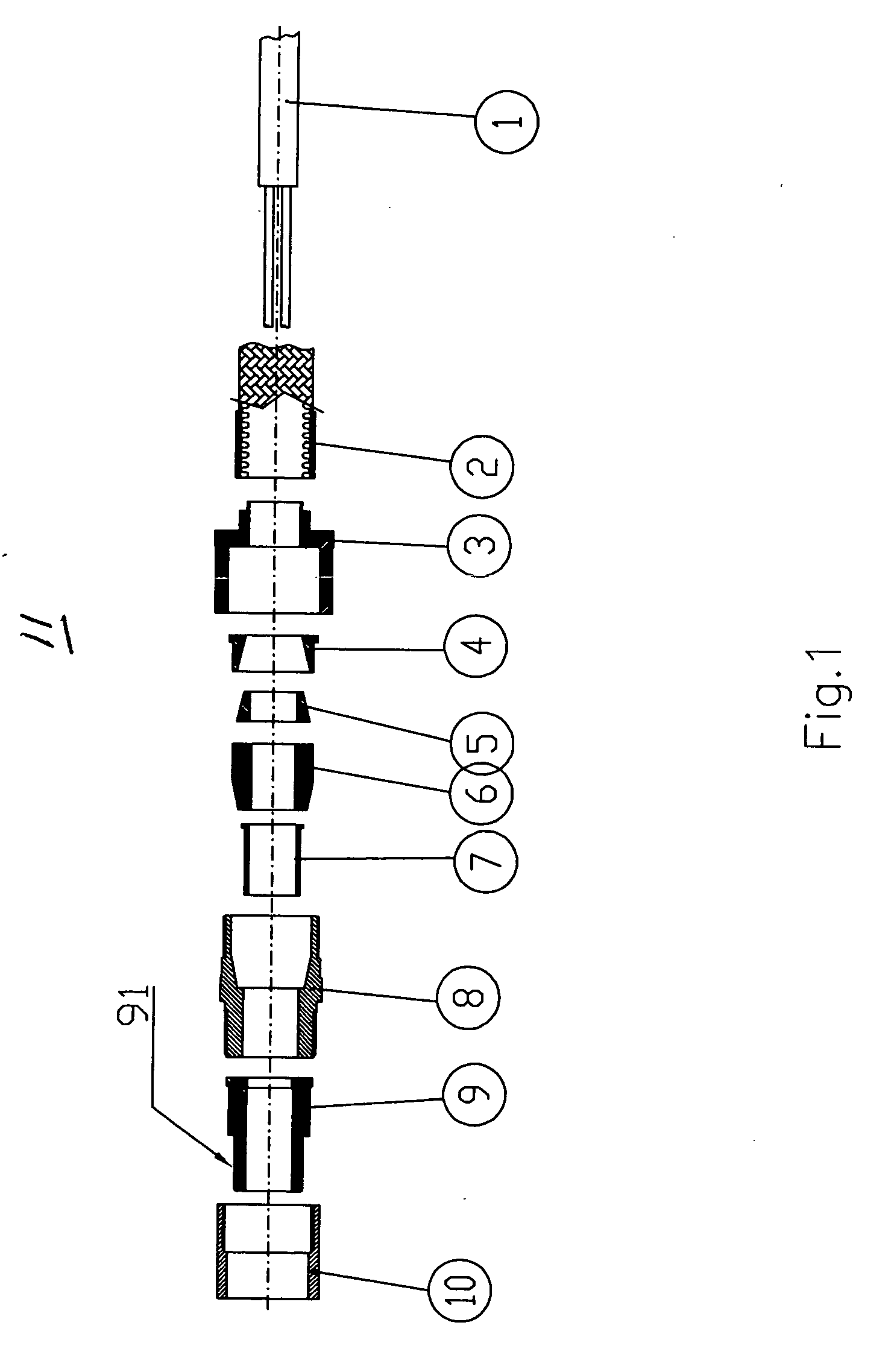
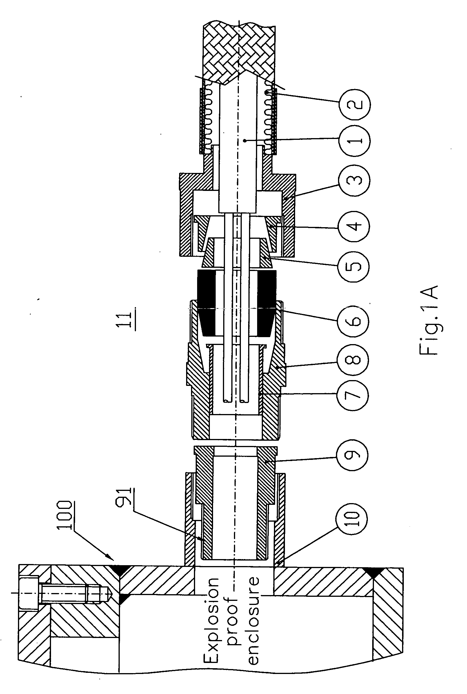
[0025]FIGS. 1, 1A, 1B and 2 show components of an explosion proof feedthrough connector (cable gland) 11 embodying an aspect of the invention. Going from right to left in FIGS. 1, 1A, and 2, the connector 11 includes a bottom capping or base nut 3, a circular bushing 4, a conical cable blocking wedge 5, a cylindrical rubber ring (grommet) 6, a cylindrical metal sleeve sealing member 7, an intermediate cable gland assembly 8, an explosion proof ring 9 with a cylindrical (tubular) threaded extension 91, and a cylindrical top nut 10 with internal threads to cap the connector. The feedthrough connector 11 is designed to couple a cable between a terminal (or terminals) external to an explosive proof enclosure 100 and a terminal (or terminals) located within the enclosure 100. For ease of description the end of the connector 11 and intermediate gland 8 adapted to receive a cable from terminals outside of the enclosure 100 will be referred to as the input (or lower) end of the connector 11...


PUM


Abstract

Explosion proof enclosures and explosion proof connectors and sensors are used to render a machine, intended to be operated in an explosive environment, explosion proof. An explosion proof connector includes an intermediate section having an input portion to receive a cable from a terminal external to an explosion proof enclosure and an output portion for passing the cable for connection to a terminal within an explosion proof enclosure. A sealing tube which extends between the input and output portions has a central opening for enabling a cable to be passed through. A sealant may be injected into the sealing tube to form an air tight connection between the cable and the inner walls of the sealing tube which inhibits a hazardous condition from passing through and around the sealing tube. An explosion proof sensor includes potting and encasing the sensor in its own explosion proof case.

Description

[0001]This invention claims priority from provisional application Ser. No. 61 / 198,539 filed Nov. 6, 2008 for Connector Apparatus And System For Explosion Proof Engine whose teachings are incorporated herein by reference.BACKGROUND OF THE INVENTION[0002]This application relates to explosion proof connectors and systems and to engines and machinery which have to be operated in an environment where explosive gases and flammable substances are present.[0003]Some industrial environments have an explosive atmosphere whereby a spark can ignite an explosion. A potential source of sparks is circuitry and machinery used to perform certain desired operations. For example, an internal combustion engine (ICE) and its associated circuits (e.g., motors) normally generate sparks, flames and / or intensely hot fumes during their operation (i.e., a hazardous condition). Inherently sparking or flame producing components are generally enclosed in an explosion proof compartment to prevent a hazardous cond...

Claims


Application Information

Patent Timeline
IPC IPC(8): F02B77/08H02G3/18
CPCH02G3/0675H02G3/088H02G15/013Y10T16/063
Inventor MIRETTI, ANGELO
Owner MIRETTI SPA
Why Eureka
Try Eureka