Drilling Apparatus and Method

Active Publication Date: 2010-05-06
HALLIBURTON ENERGY SERVICES INC
View PDF39 Cites 51 Cited by
  • Summary
  • Abstract
  • Description
  • Claims
  • Application Information

AI Technical Summary

Problems solved by technology

When the drilling string is made up of a continuous length of coiled tubing, it is relatively more difficult to rotate the entire drill string because the spool must also be rotated.
As a result, steering with a bend in the drilling string may typically only be achieved during sliding drilling, since rotary drilling will result in a constant rotatio

Method used


Image

  • Drilling Apparatus and Method
  • Drilling Apparatus and Method
  • Drilling Apparatus and Method

Examples


first embodiment

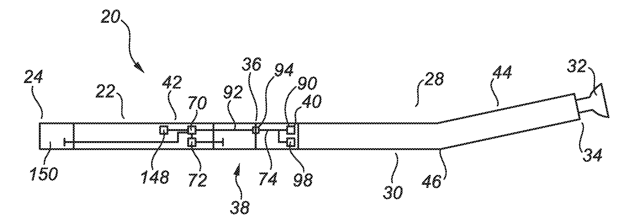
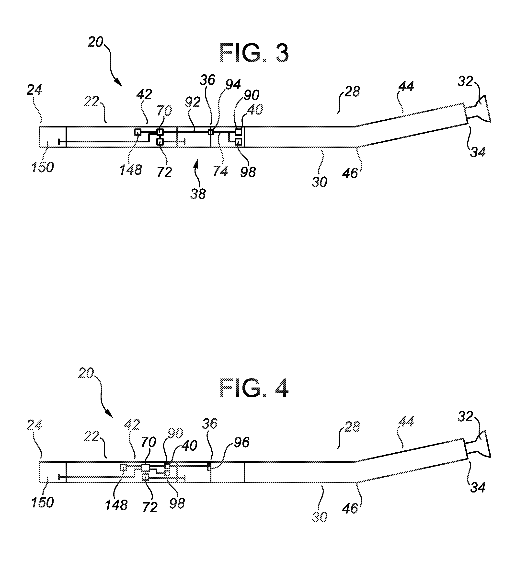
[0059]FIG. 5 provides a hydraulic circuit diagram for the reactive torque control device (38).

[0060]Referring to FIG. 5, the reactive torque control device (38) may be comprised of a pump (110) and a loop (112) containing a pumping fluid (114), wherein the pump (110) pumps the pumping fluid (114) around the loop (112). As depicted in FIG. 5, the pump (110) is driven by relative rotation between the lower assembly (28) and the upper assembly (22). In other embodiments, the pump (110) may be driven by a power source other than the relative rotation between the lower assembly (28) and the upper assembly (22).

[0061]Referring to FIG. 5, the loop (112) is comprised of a pumping resistance (116). The pumping resistance (116) loads the pump (110) and thereby impedes the relative rotation between the lower assembly (28) and the upper assembly (22). The pumping resistance (116) may be adjustable. The pumping resistance (116) may be comprised of one or more flow restrictors (118) positioned in...

second embodiment

[0066]FIG. 6 provides an hydraulic circuit diagram for the reactive torque control device (38).

[0067]Referring to FIG. 6, the reactive torque control device (38) may be further comprised of a brake (122) which is associated with the loop (112). The brake (122) may be comprised of any structure, device or apparatus which is capable of providing a braking force between the upper assembly (22) and the lower assembly (28) in order to impede or prevent relative rotation between the lower assembly (28) and the upper assembly (22). As non-limiting examples, the braking force may be a frictional force, a magnetic force, an electromagnetic force, or a viscous fluid force, and the brake (122) may be comprised of any suitable braking mechanism and / or a clutch mechanism which may be adapted to be associated with the loop (112).

[0068]As depicted in FIG. 6, the brake (122) may be comprised of a first brake part (124) associated with the upper assembly (22) and a second brake part (126) associated...


PUM


Abstract

A drilling apparatus includes an upper drill string, a lower drill string including a rotary drilling motor, an orientable rotatable connection between the drill strings, a reactive torque control device associated with the orientable rotatable connection, an orientation sensing device for providing a sensed actual orientation of the lower drill string, and a feedback control system configured to actuate the control device in response to the sensed actual orientation to achieve a target orientation of the lower drill string. A drilling method includes actuating the control device to prevent relative rotation of the drill strings, providing a sensed actual orientation of the lower drill string, comparing the sensed actual orientation with a target orientation of the lower drill string, actuating the control device to allow the lower drill string to rotate to provide the target orientation, and actuating the control device to prevent relative rotation of the drill strings.

Description

TECHNICAL FIELD[0001]An apparatus and a method for use in drilling a borehole.BACKGROUND OF THE INVENTION[0002]Drilling of subterranean boreholes is often performed by rotating a drill bit which is located at a distal end of a drilling string. The drill bit may be rotated by rotating the entire drill string from a surface location and / or by using a rotary drilling motor which is connected with the drilling string and which is located adjacent to the drill bit.[0003]The drilling string may be made up of individual joints of drilling pipe which are connected together to form the drilling string. Alternatively, the drilling string may be made up of a continuous length of coiled tubing which is stored on a large spool.[0004]When the drilling string is made up of individual joints of drilling pipe, the entire drill string may be rotated with relative ease using a rotary table or a top drive on the drilling rig. When the drilling string is made up of a continuous length of coiled tubing, ...

Claims


Application Information

Patent Timeline
IPC IPC(8): E21B44/00E21B44/02E21B7/08E21B7/04E21B47/12
CPCE21B7/067E21B47/024
Inventor HAY, RICHARD T.BOTTERELL, PAULSCHROTER, TERENCESTRILCHUK, NATHAN
Owner HALLIBURTON ENERGY SERVICES INC
Why Eureka
Try Eureka