
Combination Weigher

Active Publication Date: 2010-05-06
YAMATO
View PDF8 Cites 30 Cited by
  • Summary
  • Abstract
  • Description
  • Claims
  • Application Information

AI Technical Summary

Benefits of technology

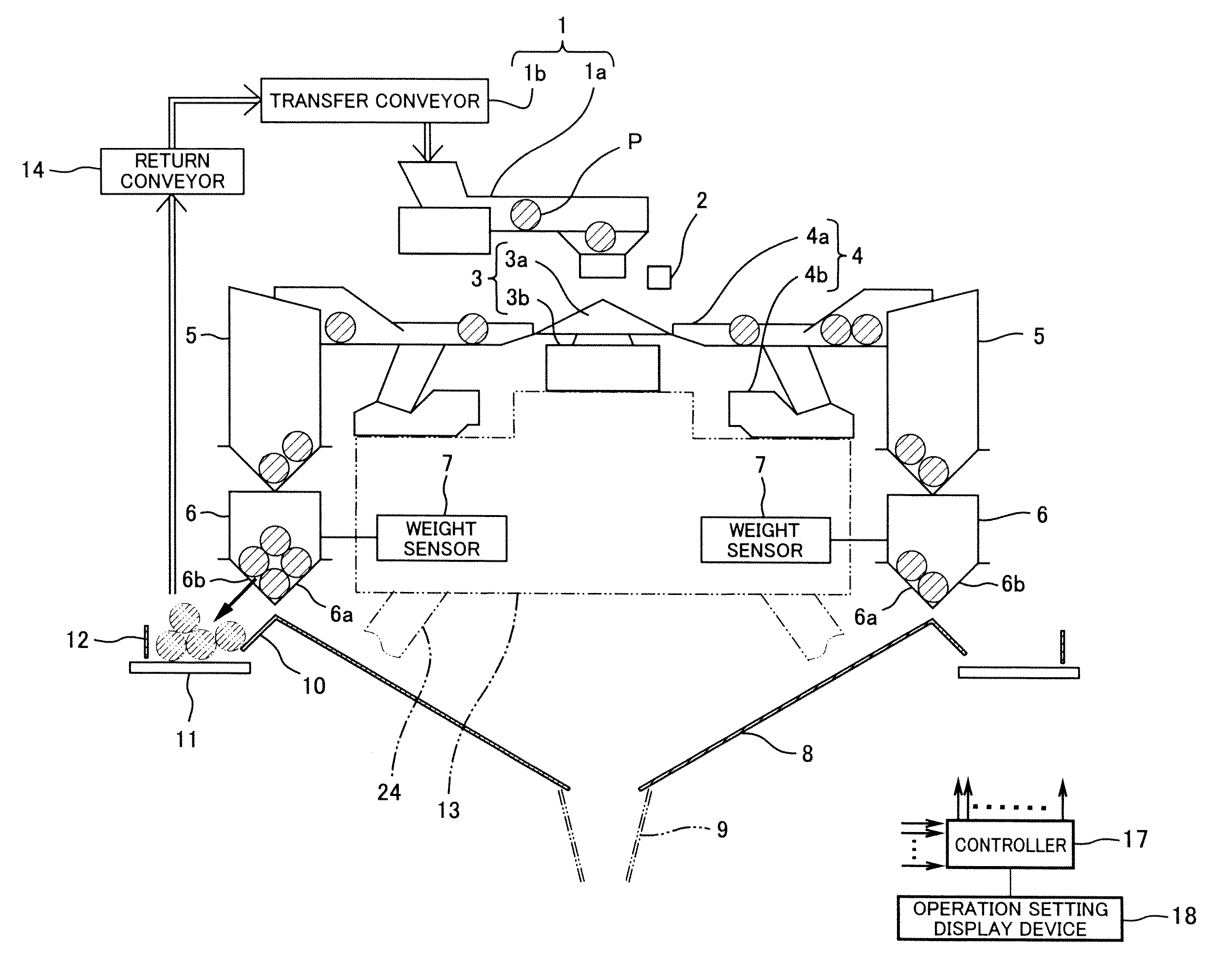
[0013]The present invention has been made with a view to solving the above described problem, and an object of the present invention is to provide a combination weigher which is capable of discharging products from a weighing hopper which is not selected for a discharge combination and from a weighing hopper which is difficult to select for the discharge combination, without manual intervention and without reducing a productive capacity.
[0015]In accordance with such a configuration, the products which have been discharged in the inward direction from the weighing hopper selected to form the discharge combination are discharged onto the collecting chute and are fed into, for example, a feed inlet of the packaging machine, from the discharge outlet of the collecting chute. On the other hand, the products which have been discharged from the weighing hopper which is determined by the recycle hopper determination means based on the predetermined recycle condition are discharged onto the recycle conveyor and are discharged from a predetermined position of the recycle conveyor. For example, the predetermined recycle condition is set such that the weight of the products which are held in the weighing hopper is a predetermined weight or larger. Under the condition, the weighing hopper which is fed with the products with an excess amount and is not selected for the discharge combination or is difficult to select for the discharge combination, is determined, so that the products can be discharged from these weighing hoppers via the recycle conveyor. That is, by providing the recycle conveyor and configuring the weighing hopper so that it is capable of discharging the products selectively to the collecting chute or to the recycle conveyor, the products can be discharged from the weighing hopper which is not selected for the discharge combination or from the weighing hopper which is difficult to select for the discharge combination via the recycle conveyor, without manual intervention and without reducing a productive capacity.
[0021]The inner guide plate enables the products which have been discharged from the weighing hopper to be guided smoothly onto the rotary table.
[0023]The outer guide plate is able to prevent the products from being ejected from the rotary table to outside.
[0034]The present invention has the above described configuration, and achieves an advantage that the combination weigher is capable of discharging products from a weighing hopper which is not selected for a discharge combination or from a weighing hopper which is difficult to select for the discharge combination without manual intervention and without reducing a productive capacity.

Problems solved by technology

It is difficult to select for the discharge combination the weighing hopper which is fed with the products whose amount is significantly larger than the target feed amount, for example, twice as large as the target feed amount.
If the weighing hopper which is fed with the products with an excess amount (hereinafter referred to as an “excess product weighing hopper”) as described above increases in number, then it becomes impossible to determine the discharge combination.
When the products are discharged from the excess product weighing hopper, the weighing hopper selected to form the discharge combination must stop discharging for a moment, causing a reduced productive capacity.

Method used


Image

  • Combination Weigher
  • Combination Weigher
  • Combination Weigher

Examples


Embodiment Construction

[0043]Hereinafter, an embodiment of the present invention will be described with reference to the drawings.

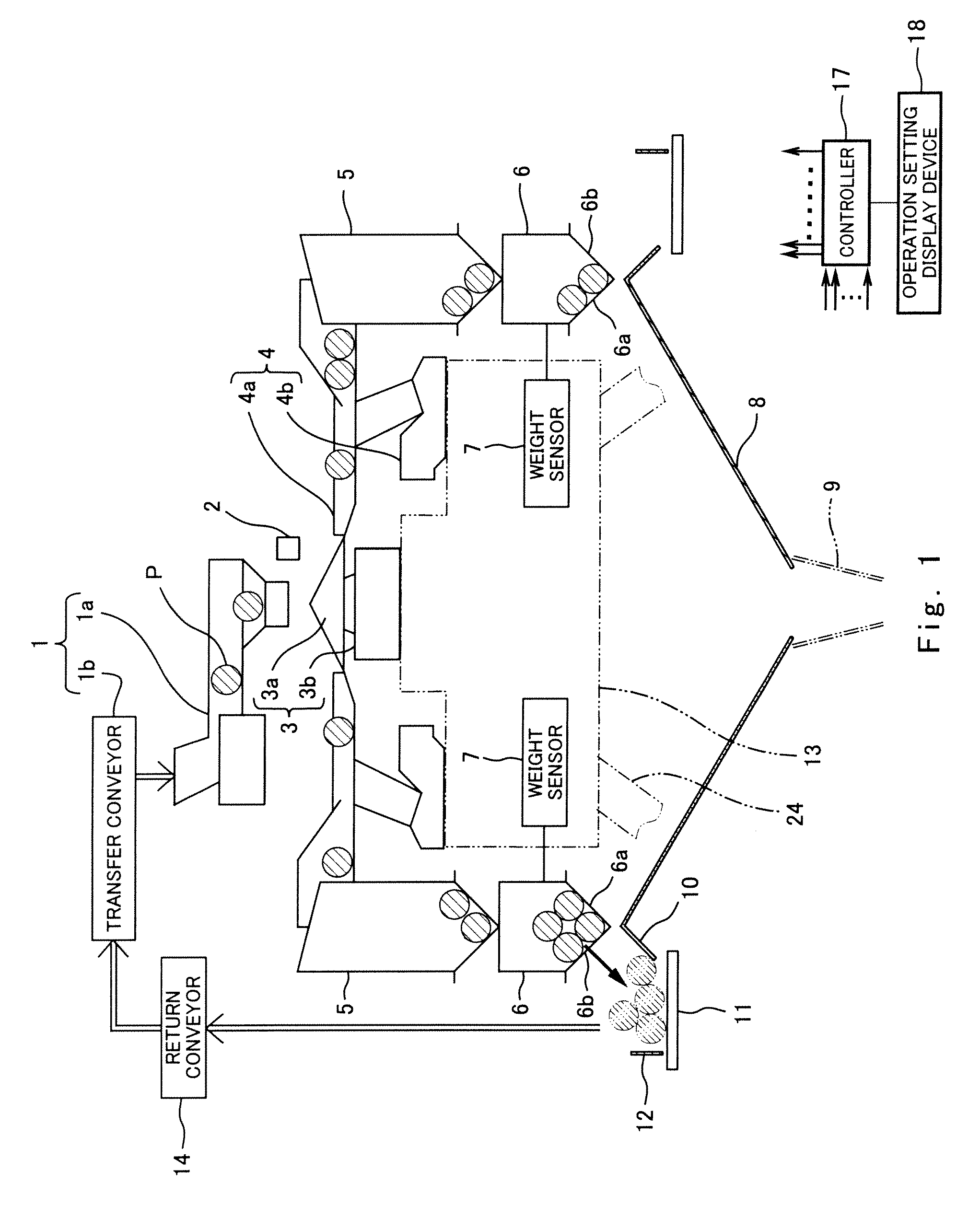
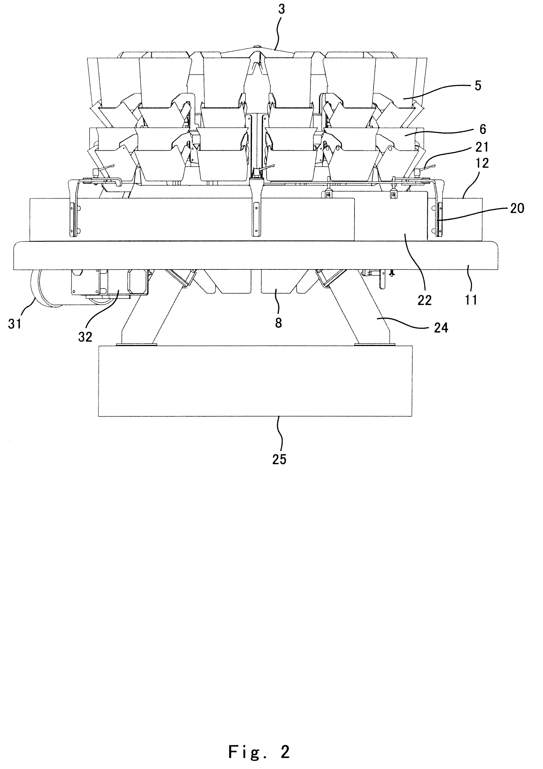
[0044]FIG. 1 is a schematic view showing a configuration of a combination weigher according to an embodiment of the present invention. FIG. 2 is a front view showing a configuration of a major part of the combination weigher. FIG. 3 is a perspective view showing a major part of the combination weigher, as viewed from above. FIG. 4 is a perspective view showing a part of a major part of the combination weigher as viewed from above. FIG. 5 is a perspective view showing a major part of the combination weigher as viewed from below. FIG. 6 is a perspective view showing a part of a major part of the combination weigher as viewed from below. FIG. 7 is a perspective view showing an external appearance of the entire combination weigher.

[0045]The combination weigher of this embodiment includes a supplying device 1 constituted by a transfer conveyor 1b and a supplying feeder 1a. The trans...


PUM


Abstract

A combination weigher of the present invention comprises a plurality of weighing hoppers which are arranged in a circular shape and are each configured to discharge the products selectively in one of two directions, a collecting chute which is configured to gather the products which have been discharged from the weighing hopper in the inward direction and to discharge the products, a recycle conveyor configured to convey the products which have been discharged from the weighing hoppers in the outward direction and have been loaded onto the recycle conveyor, a discharge means which is configured to discharge the products from the recycle conveyor; a combination calculation means which is configured to determine a discharge combination, a recycle hopper determination means configured to determine a weighing hopper whose products should be recycled, and a control means configured to cause the weighing hoppers selected to form the discharge combination to discharge the products in the inward direction, and to cause the weighing hopper determined by the recycle hopper determination means to discharge the products in the outward direction.

Description

BACKGROUND OF THE INVENTION[0001]1. Field of the Invention[0002]The present invention relates to a combination weigher which includes weighing hoppers arranged in a circular shape and feeds to a packaging machine or the like products which have been weighed.[0003]2. Description of the Related Art[0004]Typically, products which have been weighed by a combination weigher are fed to, for example, a packaging machine, and are charged into packaging bags or packaging containers. Such a combination weigher which weighs the products is configured to include weighing hoppers arranged in a circular shape or weighing hoppers arranged in a linear shape. In these configurations, for example, below the weighing hoppers, a collecting chute is disposed to gather the products which have been discharged from the weighing hoppers and to discharge the products from a discharge outlet provided at a bottom part thereof to a packaging machine or the like. In the configuration in which the weighing hopper...

Claims


Application Information

Patent Timeline
IPC IPC(8): G01G19/32
CPCG01G19/393
Inventor KIESELHORST, RALPH
Owner YAMATO
Learn More