
Apparatus, system and method for moving a vehicle from dual belt conveyor to dual belt conveyor

a technology of dual belt conveyors and equipment, applied in the direction of mechanical conveyors, cleaning apparatus with conveyors, cleaning using liquids, etc., can solve the problems of vehicle potentially being stalled, vehicle damage, and particularly problematic, so as to facilitate the transfer of a vehicle and minimize the resistance of the vehicle

Inactive Publication Date: 2010-05-06
SUNCOR ENERGY INC +1
View PDF11 Cites 39 Cited by
  • Summary
  • Abstract
  • Description
  • Claims
  • Application Information

AI Technical Summary

Benefits of technology

The invention is about a system and method for transferring a vehicle with freewheeling wheels from one conveyor to another. The system includes passive transitions and cleats that engage the wheels and push or pull them over the transitions. The method involves engaging the wheels with cleats on the conveyors, moving the conveyors in the direction of travel, and engaging the cleats on the other conveyor to push or pull the vehicle. The invention also includes a transition for transferring a freewheeling wheel between end-to-end belts in a direction of travel. The technical effects of the invention include minimizing resistance against the vehicle during transfer and facilitating unobstructed passage of the conveyors.

Problems solved by technology

Should the wheels of the vehicle be prevented from rotating, such as by placing the drivetrain in Park or one or more of the footbrake or the emergency brake being engaged, the vehicle may be damaged when engaged with the lug.
Despite warnings to the contrary, it is known that operators may place the vehicle in the locked state or the freewheeling state.
This becomes particularly problematic in unmanned car washes which utilize belt conveyors and the vehicle's operator places the vehicle in neutral.
The wheels are therefore freewheeling and can hang up in gaps at the transitions between belts, the vehicle potentially becoming stalled at the transition.
Further, the vehicle may skew if passed over the transition, particularly if the rotatable wheels are not aligned with the direction of travel.
As a further complication in belt conveyors, Applicant believes that should the wheels be placed in the locked state and the vehicle successfully reach an end of the conveyor, the vehicle may be damaged as the front wheels of the vehicle exit from the final conveyor onto a surface outside the carwash while the rear wheels remain on the moving conveyor.
It is possible that should the gap be large enough, personnel may engage with the gap, such as with their feet and severe injury is known to result.

Method used


Image

  • Apparatus, system and method for moving a vehicle from dual belt conveyor to dual belt conveyor
  • Apparatus, system and method for moving a vehicle from dual belt conveyor to dual belt conveyor
  • Apparatus, system and method for moving a vehicle from dual belt conveyor to dual belt conveyor

Examples


example a

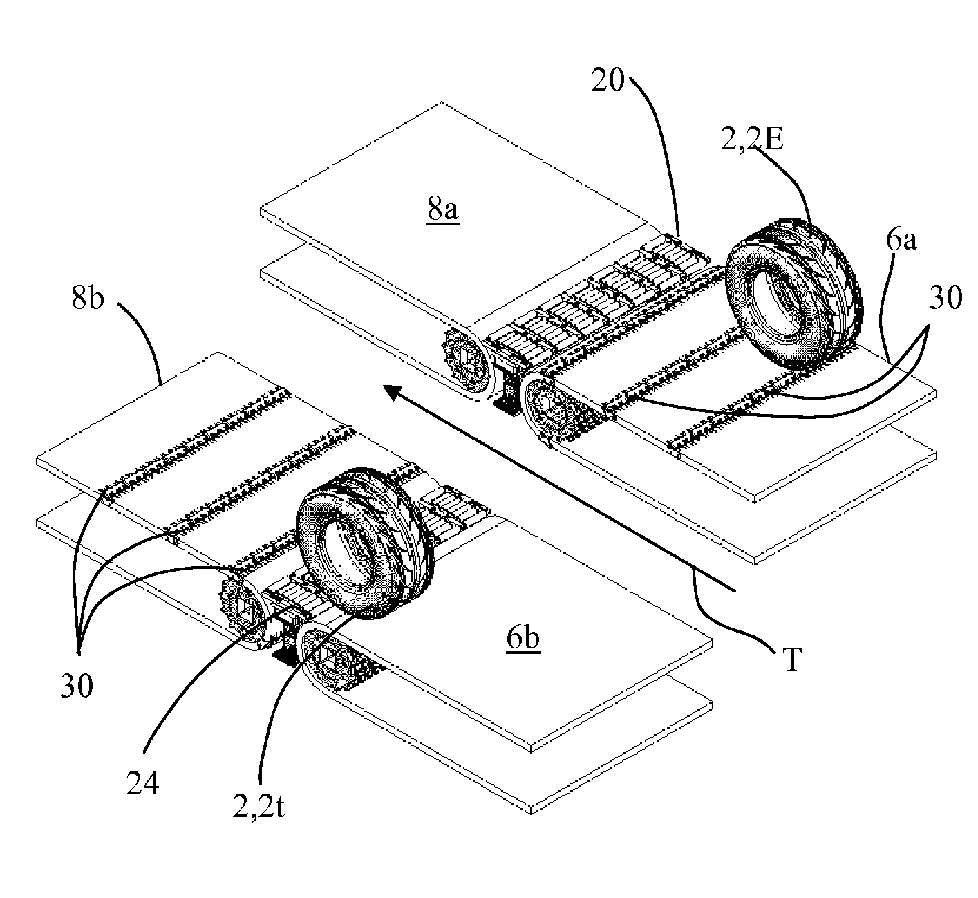
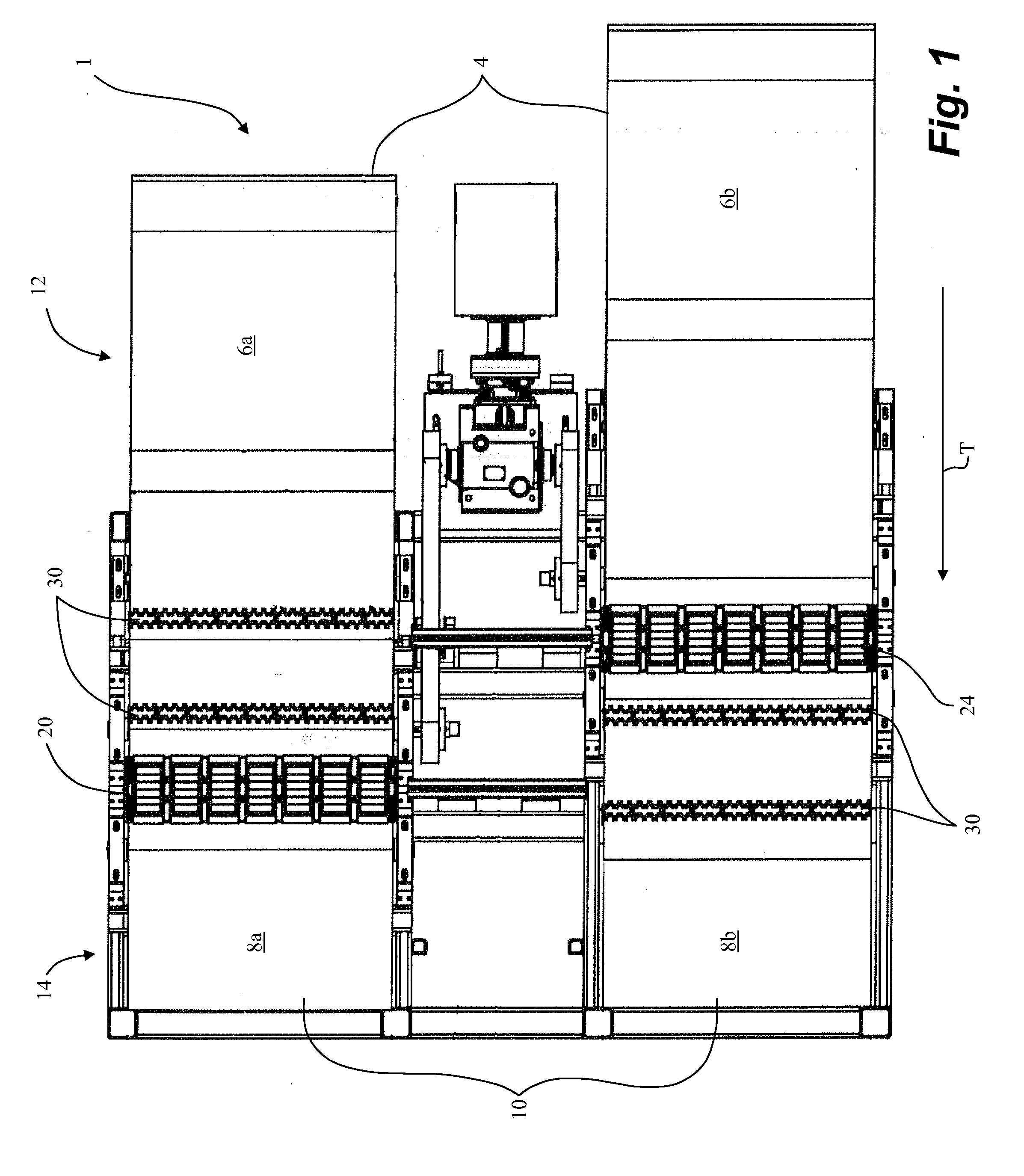
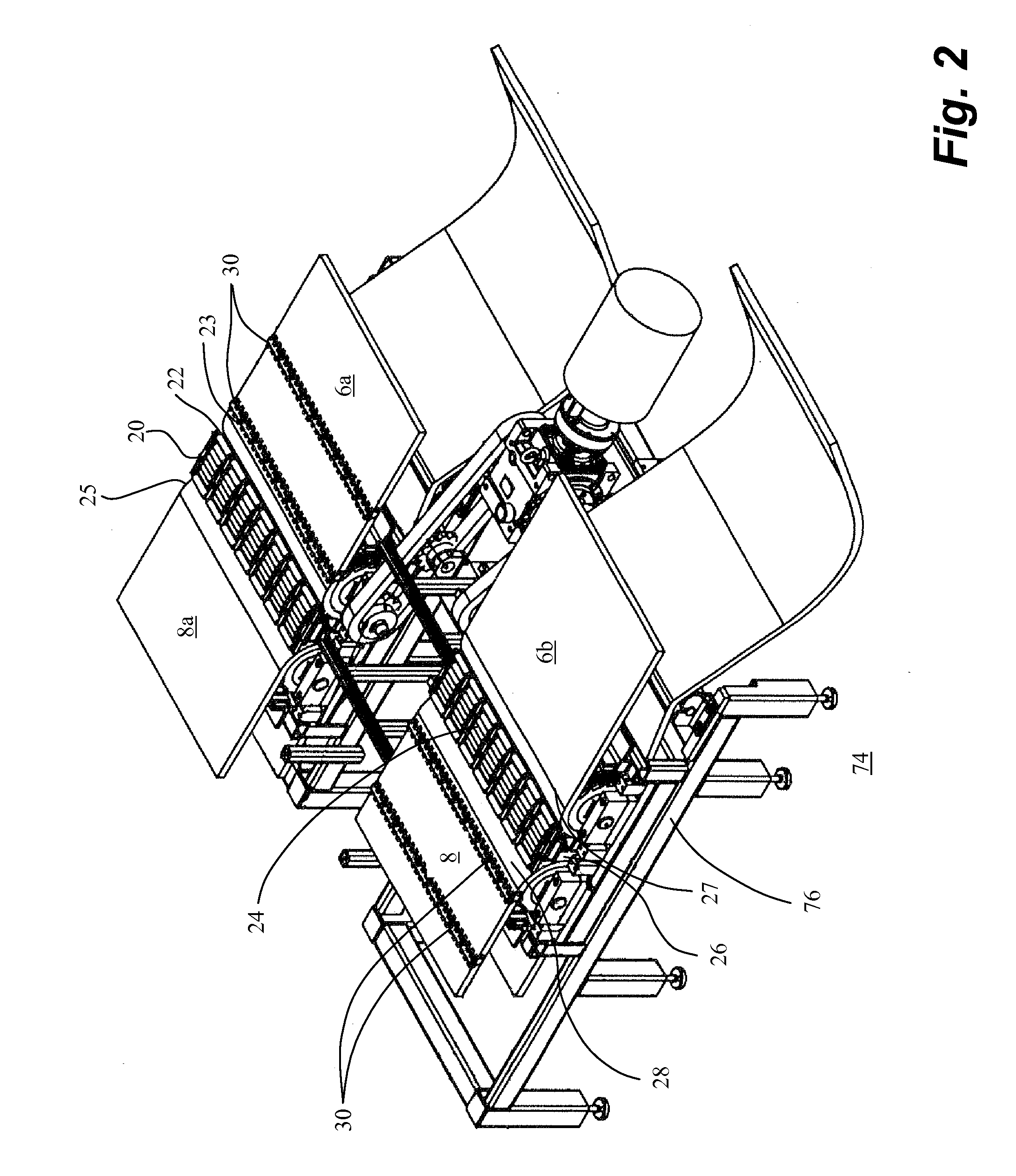
[0067]In one example, as shown in FIGS. 1-7, embodiments of the invention are used in a car wash to move a vehicle into and through a wash tunnel 70. The first pair 4 of substantially parallel endless first 6a and second 6b side belts form an entrance conveyor 12 which extends from external the wash tunnel 70 and into an entrance 72 of the wash tunnel 70 and onto which the operator drives the vehicle.

[0068]Once inside the entrance 72 of the wash tunnel 70, a second pair 10 of substantially parallel endless first 8a and second 8b side belts forms a wash conveyor 14 which is oriented end-to-end with the entrance conveyor 12. First and second transitions 20,24 according to an embodiment of the invention are supported between the first side belt 6a of the entrance conveyor 12 and the first side belt 8a of the wash conveyor 14 and the second side belt 6b of the entrance conveyor 12 and the second side belt 8b of the wash conveyor 14. The vehicle is transferred from the entrance conveyor ...

example b

[0083]Design of an optimum cleat height, as previously described, finely balances the height of the cleat so as to provide at least a minimum transitioning force to push against a wheel of the vehicle to overcome at least a first minimum resistance threshold acting against another wheel of the vehicle at either of the first or second transition.

[0084]A worst case scenario for design of the cleat height is a vehicle having small wheels, where more of the wheel is engaged by the gaps and therefore the resistance is greater to the forward movement of the wheel over the transitions.

[0085]In one embodiment of the invention, an optimum cleat height was determined for a 1989 Pontiac Firefly having a tire size of 33 cm (13 inches).

[0086]As Table B illustrates, increasing the cleat height to attempt to achieve a greater pushing or transitioning force requires an increase in the discharge and intake gaps so as to permit the higher cleat to pass thereby. The increase in the gap size required t...


PUM


Abstract

A system and method for transferring a vehicle from a first dual belt conveyor to a second dual belt conveyor utilizes transitions between the belts of the first and second conveyors which are offset along a direction of travel. The offset transitions result in only one wheel of the vehicle at a time crossing a transition. The transitions utilize fixed rollers positioned on either side of a plurality of recirculation rollers. The fixed rollers minimize the gap between the ends of the belts and the transitions while permitting the belts, particularly with cleats, to pass by the fixed rollers.

Description

FIELD OF THE INVENTION[0001]Embodiments of the invention are directed to apparatus, systems and methods for transferring a vehicle from one dual belt conveyor to another dual belt conveyor and more particularly from at least a dual belt entrance conveyor of a car wash to a dual belt wash conveyor in the car wash wherein the vehicle may be in a variety of states including but not limited to park, neutral, foot brake engaged or emergency brake engaged.BACKGROUND OF THE INVENTION[0002]Conveyance systems are well known for moving vehicles along a direction of travel, such as along an assembly line in an automotive assembly plant or through a car wash tunnel.[0003]One type of conveyor utilized particularly in conventional car washes is a chain conveyor having spaced, large, upwardly extending lugs which positively engage a wheel of the vehicle and act to drag the vehicle through the car wash tunnel. The vehicle's transmission is placed in neutral to permit the wheels of the vehicle to ro...

Claims


Application Information

Patent Timeline
Patent Type & Authority Applications(United States)
IPC IPC(8): B65G47/54B65G15/44B65G37/00B60S3/04
CPCB60S3/004B65G17/24B65G47/66
Inventor BARREYRE, BERNARD G.MAI, STEVEN W.BUNSTON, BRETT
Owner SUNCOR ENERGY INC
Learn More