

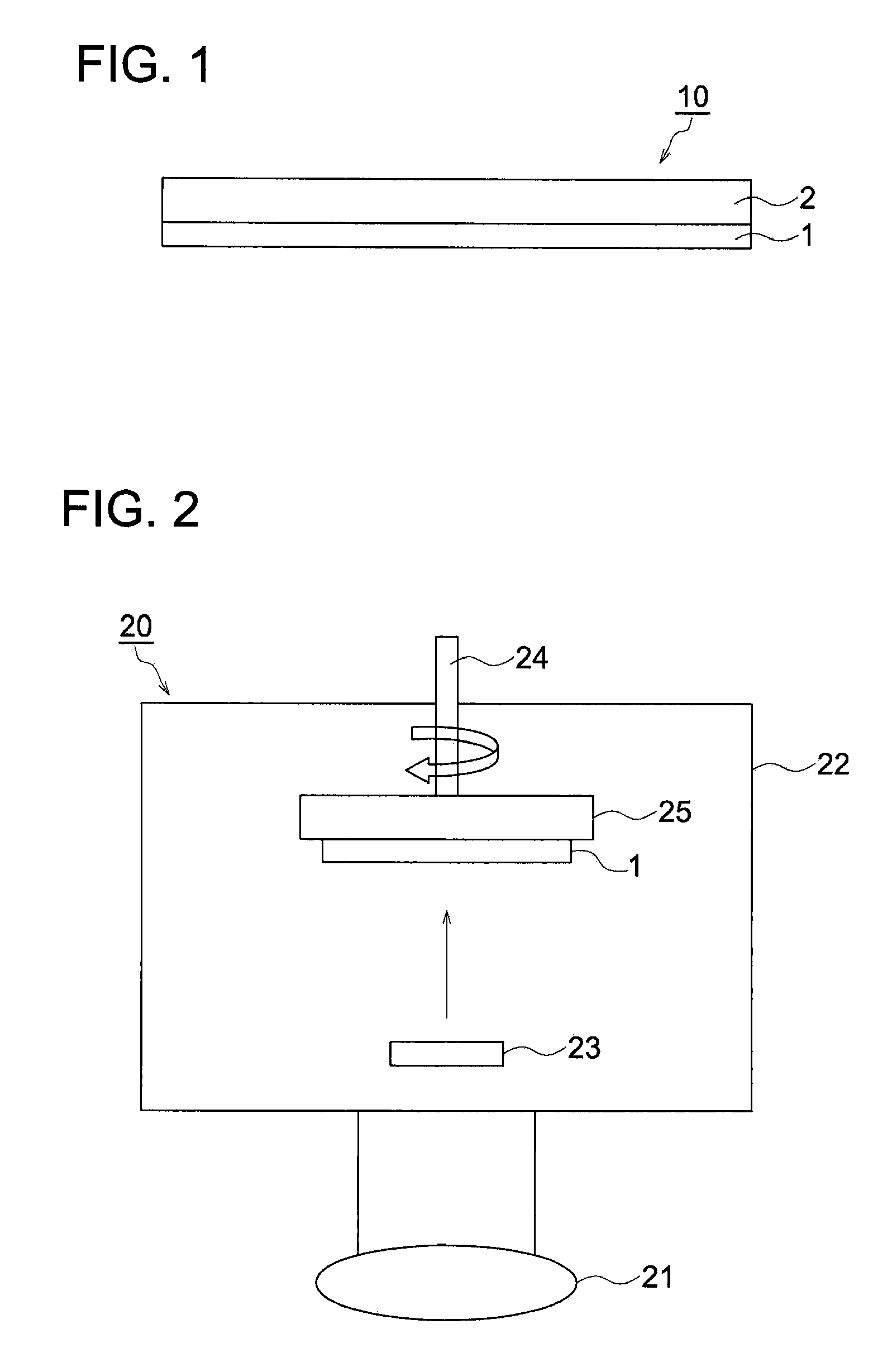
Scintillator plate
a technology of scintillator and plate, which is applied in the direction of conversion screens, nuclear engineering, luminescent compositions, etc., can solve the problems of insufficient spatial resolution, insufficient image sharpness, and inability to realize free image processing or instantaneous image transfer, etc., and achieves superior sharpness and luminance.
- Summary
- Abstract
- Description
- Claims
- Application Information
AI Technical Summary
Benefits of technology
Problems solved by technology
Method used
Image

Examples
example 1
Preparation of Substrate
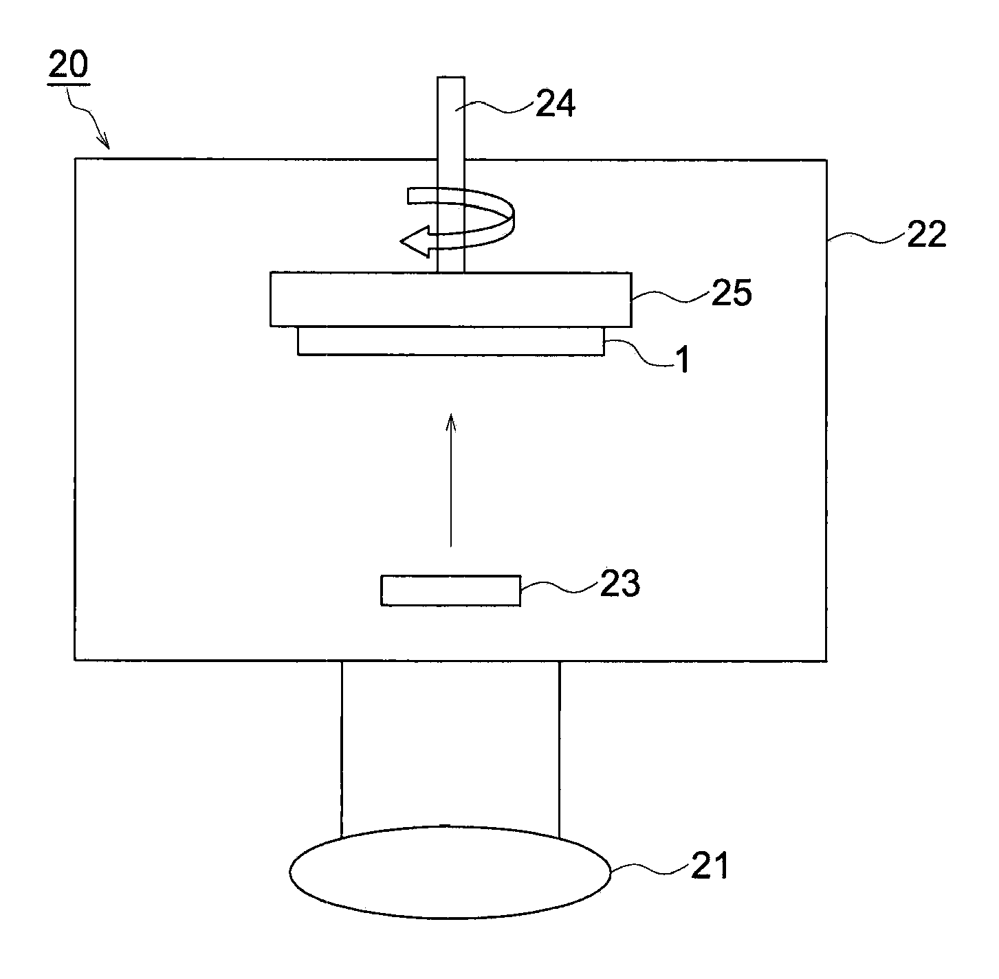
[0066]A 0.5 mm thick aluminum sheet was cut to 10×10 cm to be used for a substrate.
Preparation of Scintillator Layer
[0067]There were prepared evaporation materials which were each composed of cesium iodide and thallium iodide (TlI), as the raw activator material, at a concentration of 2.4 mol % or 0.3 mol % of CsI. The prepared evaporation materials were each placed into separate resistance heating crucibles. The substrate was provided on a rotating substrate holder and the distance between the substrate and the evaporation source was adjusted to 400 mm.
[0068]Subsequently, the inside of the vapor deposition apparatus was evacuated and then, Ar gas was introduced thereto to control an evacuation degree to 0.1 Pa, thereafter, the temperature of the substrate was maintained at 200° C., while rotating the substrate at a rate of 10 rpm. Then, the resistance heating crucible, having a material of a higher Tl concentration was heated to allow a phosphor for a scinti...
example 2
Preparation of Substrate
[0069]Preparation of the substrate was conducted in the same manner as Example 1.
Preparation of Scintillator Layer
[0070]Thallium iodide (TlI) as an raw activator material was mixed with cesium iodide (CsI). There were prepared evaporation materials which were each composed of cesium iodide and thallium iodide (TlI) at a concentration of 1.5 mol % or 0.3 mol % of cesium iodide. The prepared evaporation materials were each placed into separate resistance heating crucibles. The substrate was provided on a rotating substrate holder and the distance between the substrate and the evaporation source was adjusted to 400 mm.
[0071]Subsequently, the inside of a vapor deposition apparatus was evacuated and then, Ar gas was introduced thereto to control an evacuation degree to 0.1 Pa, thereafter, the temperature of the substrate was maintained at 200° C., while rotating the substrate at a rate of 10 rpm. Then, the resistance heating crucible having a material of a higher ...
example 3
Preparation of Substrate
[0072]Preparation of the substrate was conducted in the same manner as Example 1.
Preparation of Scintillator Layer
[0073]Thallium iodide (TlI) as an raw activator material was mixed with cesium iodide (CsI). There were prepared evaporation materials which were each composed of cesium iodide and thallium iodide (TlI) at a concentration of 3.1 mol % or 0.3 mol % of cesium iodide. The prepared evaporation materials were each placed into separate resistance heating crucibles. The substrate was provided on a rotating substrate holder and the distance between the substrate and the evaporation source was adjusted to 400 mm.
[0074]Subsequently, the inside of a vapor deposition apparatus was evacuated and then, Ar gas was introduced thereto to control an evacuation degree to 0.1 Pa, thereafter, the temperature of the substrate was maintained at 200° C., while rotating the substrate at a rate of 10 rpm. Then, the resistance heating crucible having a material of a higher ...
PUM
 Abstract
- wherein A is an average activator concentration of the scintillator layer and B is an activator concentration in a region of the scintillator layer from the reflection layer side to the position of L/5.
Description
Claims
Application Information