AC motor driving circuit and electric car driving circuit

a technology of ac motor and driving circuit, which is applied in the direction of motor/generator/converter stopper, dynamo-electric converter control, electric commutator, etc., can solve the problems of lowering the efficiency of power conversion between the dc power supply and the ac motor generator, and the motor generator mgb>1/b> cannot perform the desired drive control of the motor generator, so as to improve conversion efficiency and prevent current. , the effect o

Active Publication Date: 2010-05-06
FUJI ELECTRIC CO LTD
View PDF2 Cites 8 Cited by
  • Summary
  • Abstract
  • Description
  • Claims
  • Application Information

AI Technical Summary

Benefits of technology

[0009]Therefore, an object of the invention is to reduce loss due to a switch to thereby prevent power conversion efficiency from being lowered.
[0014]According to the invention, a switch (e.g., S1 in FIG. 8) for preventing backflow from occurring at the operating time of the matrix converter can be dispensed with so that wiring for this portion can be shortened to thereby reduce wiring inductance. For this reason, it is possible to reduce a surge voltage, which is applied to the bidirectional switches and the switches in the power conversion circuit according to the present invention, when these switches are turned on / off, compared with the switches (e.g., Q31 to Q36 in FIG. 8) in the voltage source inverter (e.g., 36 in FIG. 8) according to the prior art. As a result, it is possible to reduce the size of a snubber circuit for snubbing the surge voltage.
[0016](1) When the matrix converter is operated to perform power conversion between the AC power supply and the AC motor, the bidirectional switches in the power conversion circuit provided between the DC power supply and the AC motor are turned off. As a result, a current can be prevented from flowing from the AC motor into the DC power supply even when an input line voltage of the AC motor is higher than an output voltage of the DC power supply. Moreover, the power conversion circuit has the same configuration as that of the voltage source inverter in which switches back-to-back connected to diodes respectively and bidirectional switches are provided as arms respectively. Accordingly, when these arms perform switching in the same manner as in the voltage source inverter, power conversion can be made between the DC power supply and the AC motor. On this occasion, the switch (e.g., S1 in FIG. 8) used in the prior art can be dispensed with so that loss can be reduced to thereby improve conversion efficiency.
[0017](2) The first period in which the matrix converter performs power conversion between the AC power supply and the AC motor and the second period in which the power conversion circuit performs power conversion between the DC power supply and the AC motor are controlled in a time division manner. As a result, the AC motor can be driven by both the electric power of the AC power supply and the electric power of the DC power supply. On this occasion, as described above, because the switches and the bidirectional switches in the power conversion circuit are turned off during the first period, a current can be prevented from flowing into the DC power supply even when an input line voltage of the AC motor exceeds an output voltage of the DC power supply. Similarly, because the bidirectional switches in the matrix converter are turned off during the second period, a current can be prevented from flowing into the AC power supply.
[0018](3) In an electric car driving circuit for a hybrid car or the like, it is necessary to mount the circuit in a limited space. In this invention, because conversion efficiency between the DC power supply and the AC motor increases, a large output circuit can be mounted so that accelerating / decelerating performance of the electric car can be improved.

Problems solved by technology

As a result, there is a possibility that the motor generator MG1 cannot perform desired drive control of the motor generator MG2.
Hence, there is a problem that loss occurring due to the switch S1 results in lowering of efficiency in power conversion between the DC power supply and the AC motor generator MG2.

Method used


Image

  • AC motor driving circuit and electric car driving circuit
  • AC motor driving circuit and electric car driving circuit
  • AC motor driving circuit and electric car driving circuit

Examples


Embodiment Construction

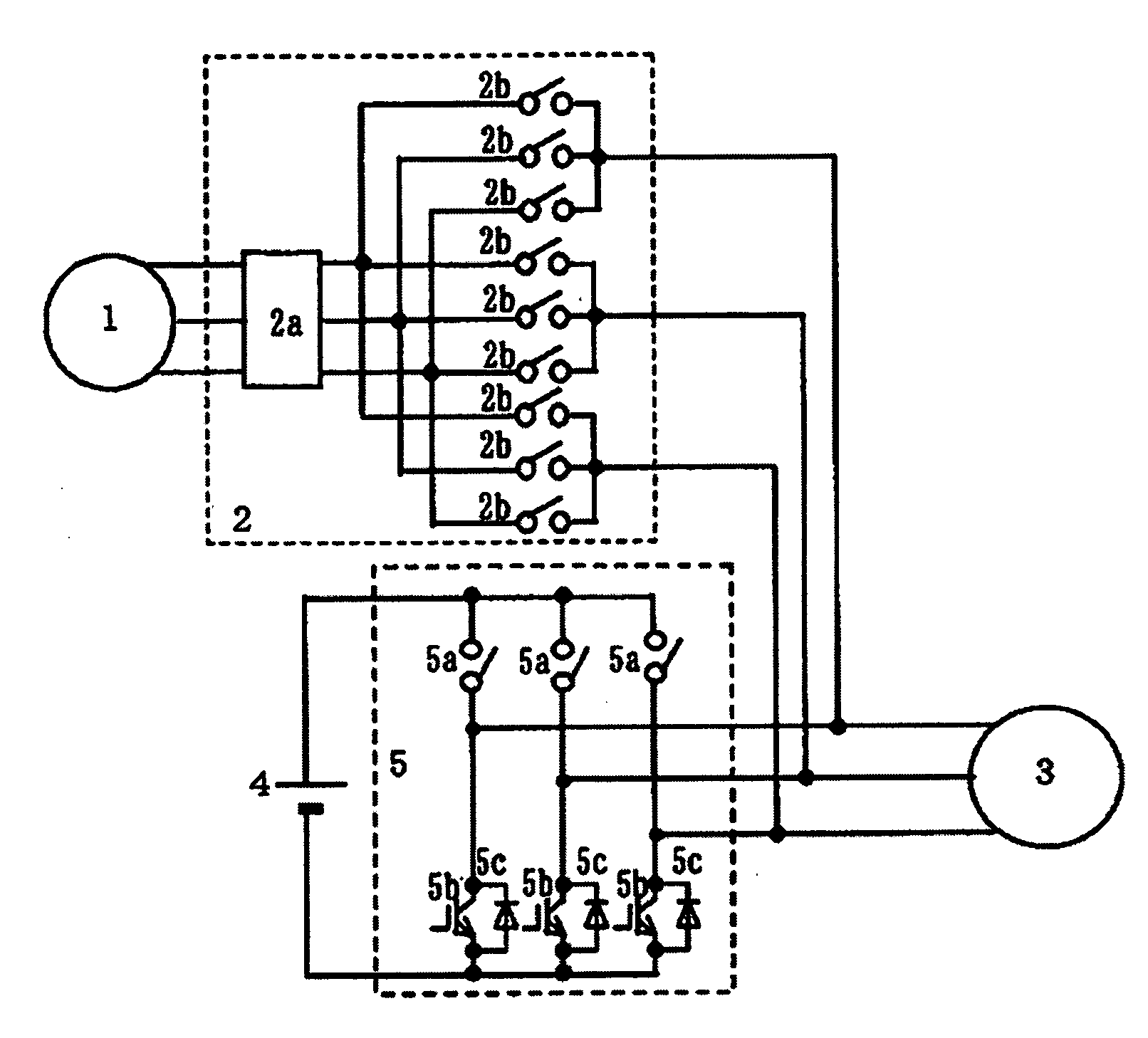
[0027]FIG. 1 is a configuration diagram showing an embodiment of the invention.

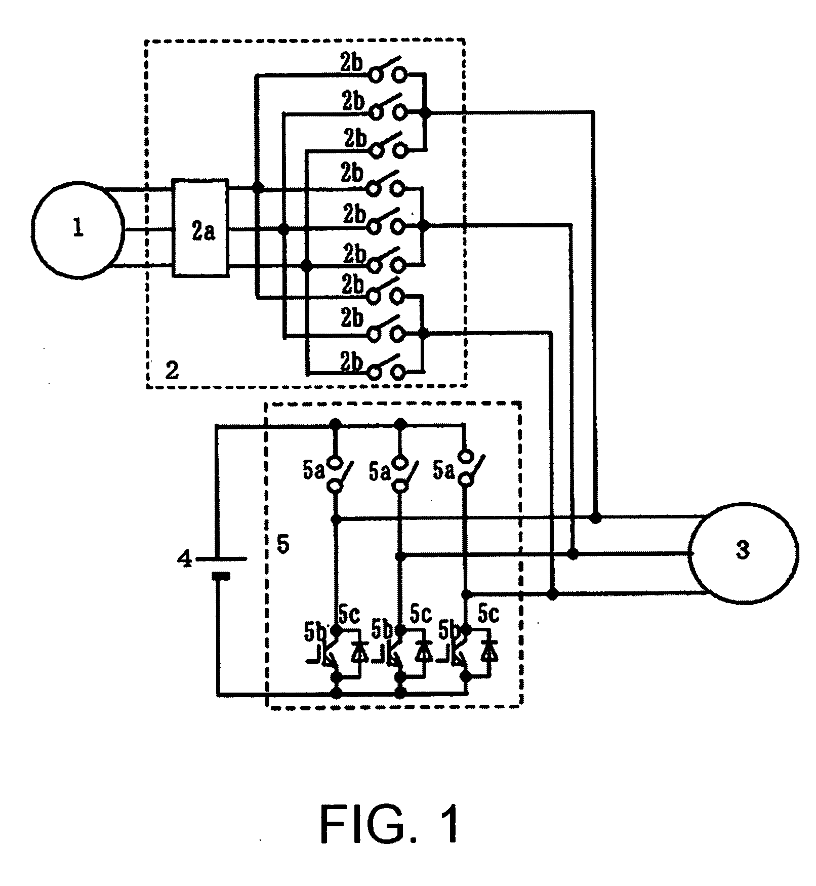
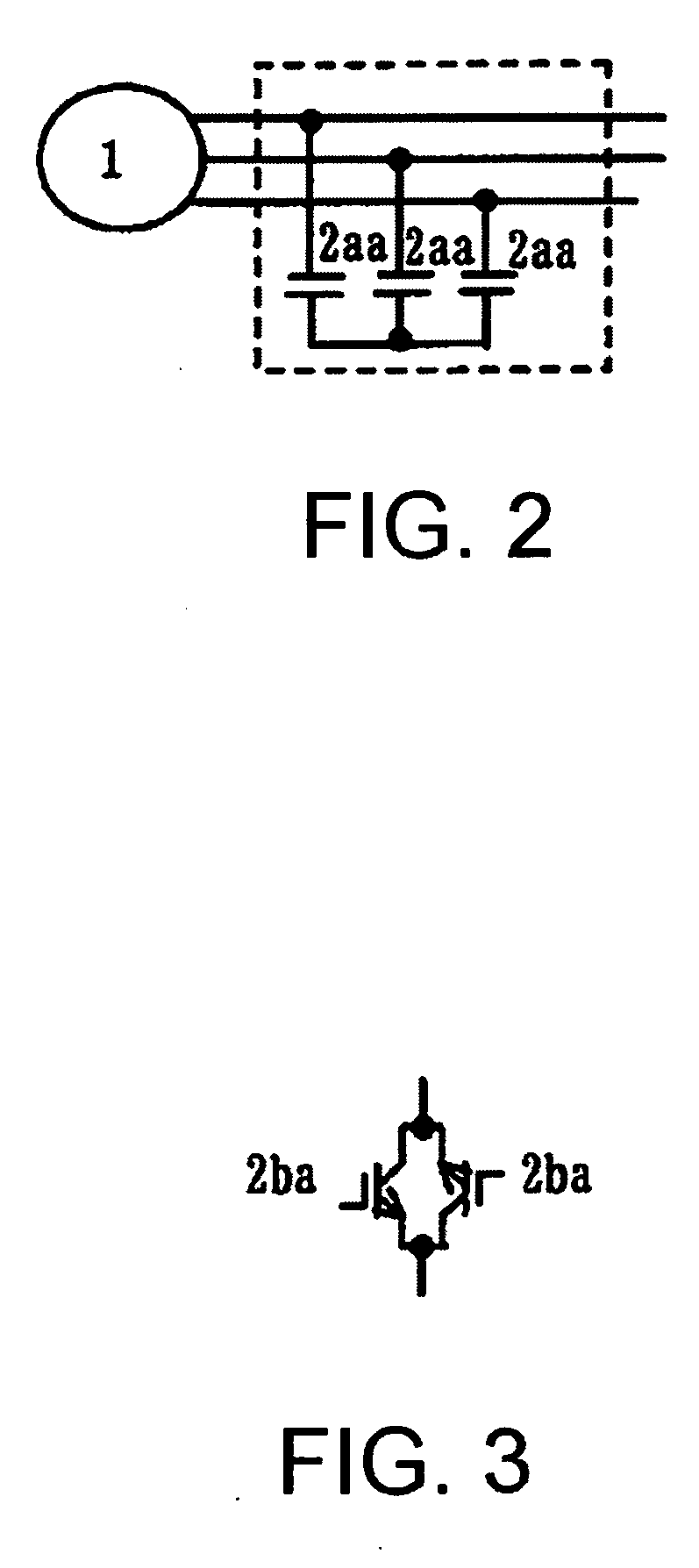
[0028]As shown in FIG. 1, in this embodiment, a matrix converter 2 is connected to an output of a three-phase AC power supply 1 so that an AC motor 3 is driven by an output of the matrix converter 2. The matrix converter 2 has a filter circuit 2a, and nine bidirectional switches 2b connected to an output of the filter circuit 2a. A storage battery 4 is used as a DC power supply capable of feeding and absorbing electric power to the outside. A power conversion circuit 5 is made of three circuits, which have unidirectional switches (hereinafter simply referred to as switches) 5b back-to-back connected to diodes 5c respectively, and bidirectional switches 5a series-connected to the switches 5b respectively. Series connection junctions between the switches 5b and the bidirectional switches 5a are connected to input phases of the AC motor 3, respectively. The other terminal of each bidirectional switch 5a is c...


PUM


Abstract

In an AC motor driving circuit from an AC power supply and a DC power supply, a matrix converter and a power conversion circuit are provided. The matrix converter is connected between an output of the AC power supply and an input of the AC motor. In the power conversion circuit, switches back-to-back connected to diodes, and bidirectional switches are series-connected, respectively. Connection junctions between the switches and the bidirectional switches are connected to the input phases of the AC motor, respectively. The other terminal of each switch is connected to one terminal of the DC power supply while the other terminal of each bidirectional switch is connected to the other terminal of the DC power supply. In this manner, the number of switches through which electric power passes at the time of operation is reduced so that loss can be reduced. Accordingly, power conversion efficiency can be improved.

Description

[0001]This application claims priority from Japanese patent application serial number 2008-280068, filed on Oct. 30, 2008, hereby incorporated by reference herein.BACKGROUND OF THE INVENTION[0002]1. Field of the Invention[0003]The present invention relates to an AC motor driving circuit which includes an AC power supply and a DC power supply capable of feeding and absorbing electric power and which drives an AC motor, and an electric car driving circuit using the AC motor driving circuit.[0004]2. Description of the Related Art[0005]For an AC motor driving circuit of this kind, there is previously known a circuit shown in FIG. 8 (e.g. JP-A-2005-318731).[0006]The circuit uses a matrix converter 38 to achieve power conversion between motor generators MG1 and MG2. The matrix converter 38 is composed of nine switches arranged as a three by three switch matrix (switches SAa to SCc). A storage battery 12, a chopper 32 and a capacitor C2 form a DC power supply capable of feeding and absorbi...

Claims


Application Information

Patent Timeline
Patent Type & Authority Applications(United States)
IPC IPC(8): H02P6/08H02P6/14H02P3/14B60L9/18B60L50/15H02M5/297H02P25/026H02P25/22H02P27/08H02P27/16
CPCB60L2210/20H02M1/10H02M5/4585Y02T10/7005B60L50/51Y02T10/725Y02T10/70B60L50/13Y02T10/7077Y02T10/7072Y02T10/72
Inventor IWAHORI, MICHIOGEKINOZU, MASAKAZU
Owner FUJI ELECTRIC CO LTD
Why Eureka
Try Eureka