
Apparatus for enabling two elements to share a common feed

a technology of antenna elements and feeds, applied in electrical apparatus, antenna details, antennas, etc., can solve problems such as difficulty in fitting all of the circuitry required for multi-band operation into a single devi

Active Publication Date: 2010-05-06
NOKIA TECHNOLOGLES OY
View PDF13 Cites 14 Cited by
  • Summary
  • Abstract
  • Description
  • Claims
  • Application Information

AI Technical Summary

Benefits of technology

[0010]The apparatus enable the operational bandwidth of an antenna element to be increased so that an antenna can be used to communicate in a number of frequency bands rather than using a different antenna for each band. Some embodiments may have a multi-low-band antenna and / or a multi-high-band antenna.

Problems solved by technology

It may be difficult to fit all of the circuitry required for multi-band operation into a single device.

Method used


Image

  • Apparatus for enabling two elements to share a common feed
  • Apparatus for enabling two elements to share a common feed
  • Apparatus for enabling two elements to share a common feed

Examples


Embodiment Construction

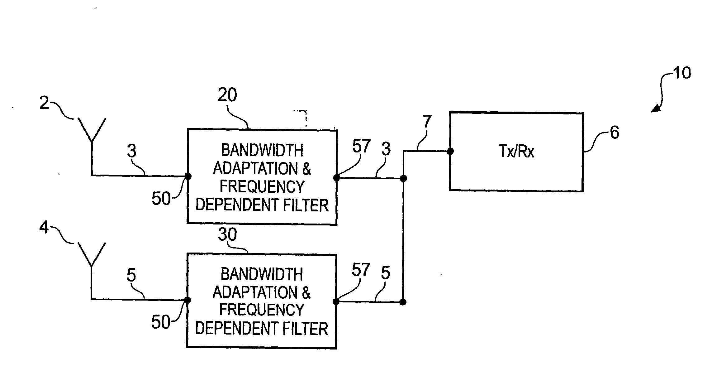
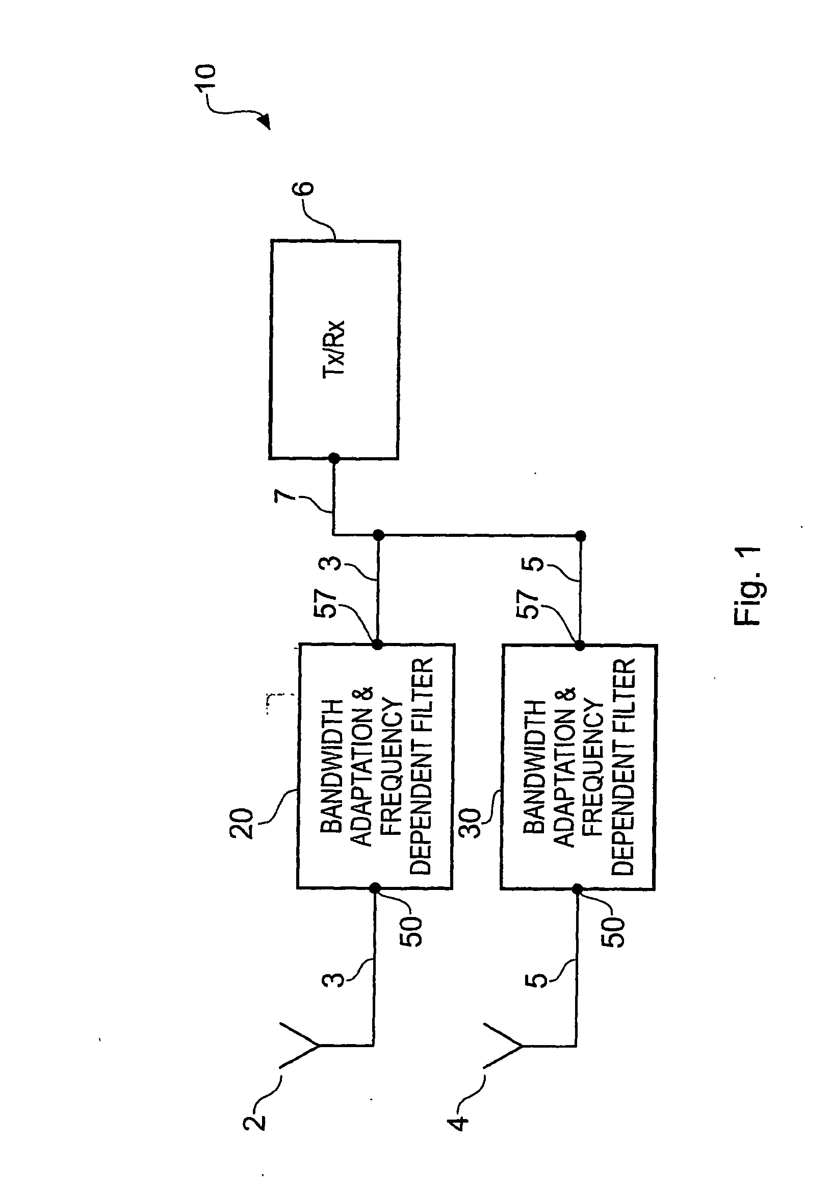
[0017]FIG. 1 schematically illustrates a radio frequency system or apparatus 10 that comprises: a first antenna element 2; a second antenna element 4; radio frequency circuitry 6; low-band bandwidth adaptation and frequency dependent filter circuitry 20; and high-band bandwidth adaptation and frequency dependent filter circuitry 20.

[0018]The system or apparatus 10 may, for example, be a mobile cellular telephone, a base station in a mobile cellular telecommunications system, a wireless communications device, a hand-portable electronic device etc or a module for use in any of the foregoing.

[0019]The first antenna element 2 in this example is operable at frequencies within a low-band frequency range of the order 1 GHz.

[0020]The first antenna element 2 is RLC series resonant at a first frequency within the low-band frequency range. The ‘native’ characteristics of the first antenna are adapted by circuitry 20 to broaden the antenna's operational bandwidth by, for example, introducing ad...


PUM


Abstract

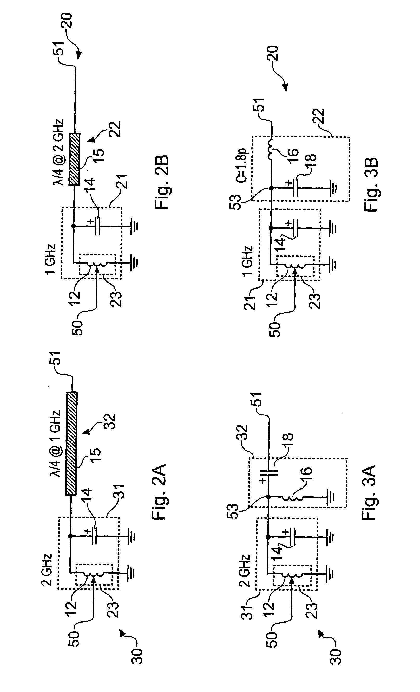
An apparatus including a first antenna element operable at least one frequency within a first frequency range; a second antenna element operable at least one frequency within a second frequency range; radio frequency circuitry electrically connected to the first antenna element via a first electrical path and electrically connected to the second antenna element via a second electrical path, wherein the first and second electrical paths are common where they connect to the radio frequency circuitry; a first frequency-dependent filter arrangement, within the first electrical path, arranged to accept frequencies within the first frequency range and reject frequencies within the second frequency range; a first impedance level transformation arrangement, having a first tapped inductor, within the first electrical path; and a second frequency-dependent filter arrangement, within the second electrical path, arranged to accept frequencies within the second frequency range and reject frequencies within the first frequency range.

Description

FIELD OF THE INVENTION[0001]Embodiments of the present invention relate to an apparatus for enabling two antenna elements to share a common feed.BACKGROUND TO THE INVENTION[0002]It is often desirable to reduce the size of electronic communication devices.[0003]In mobile cellular telecommunication it may be necessary to have separate and distinct antennas and radio frequency circuitry for each radio frequency band. It may be difficult to fit all of the circuitry required for multi-band operation into a single device.[0004]There is therefore at present considerable interest in reducing the number of components.[0005]It would be desirable to reduce the number of components in a radio communications device and achieve multi-band operation.BRIEF DESCRIPTION OF THE INVENTION[0006]According to an embodiment of the present invention there is provided an apparatus comprising: a first antenna element operable at least one frequency within a first frequency range; a second antenna element oper...

Claims


Application Information

Patent Timeline
Patent Type & Authority Applications(United States)
IPC IPC(8): H01Q21/30
CPCH01Q1/243H03H7/38H01Q21/30H03H7/40
Inventor RANTA, TERO TA
Owner NOKIA TECHNOLOGLES OY
Learn More