Divergence ratio distance mapping camera

a technology of distance mapping and divergence ratio, which is applied in the field of three-dimensional information detection methods and systems, can solve the problems of limited triangulation methods, inability to provide real-time operation of television cameras, and limited time of flight methods

Inactive Publication Date: 2010-05-06
IIZUKA KEIGO
View PDF40 Cites 18 Cited by
  • Summary
  • Abstract
  • Description
  • Claims
  • Application Information

AI Technical Summary

Problems solved by technology

This triangulation method is limited in that it is too slow and generally can not provide for the real-time operation of a television camera.
While depth resolution can be within micrometers, time of flight methods can be limited to the order of minutes in providing a depth map of a target object.

Method used


Image

  • Divergence ratio distance mapping camera
  • Divergence ratio distance mapping camera
  • Divergence ratio distance mapping camera

Examples


Embodiment Construction

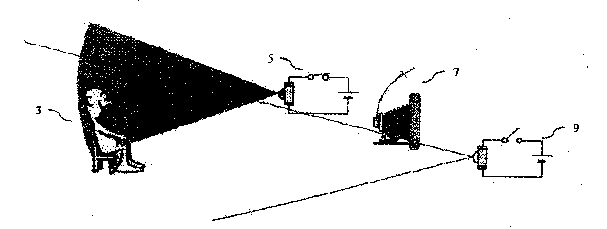
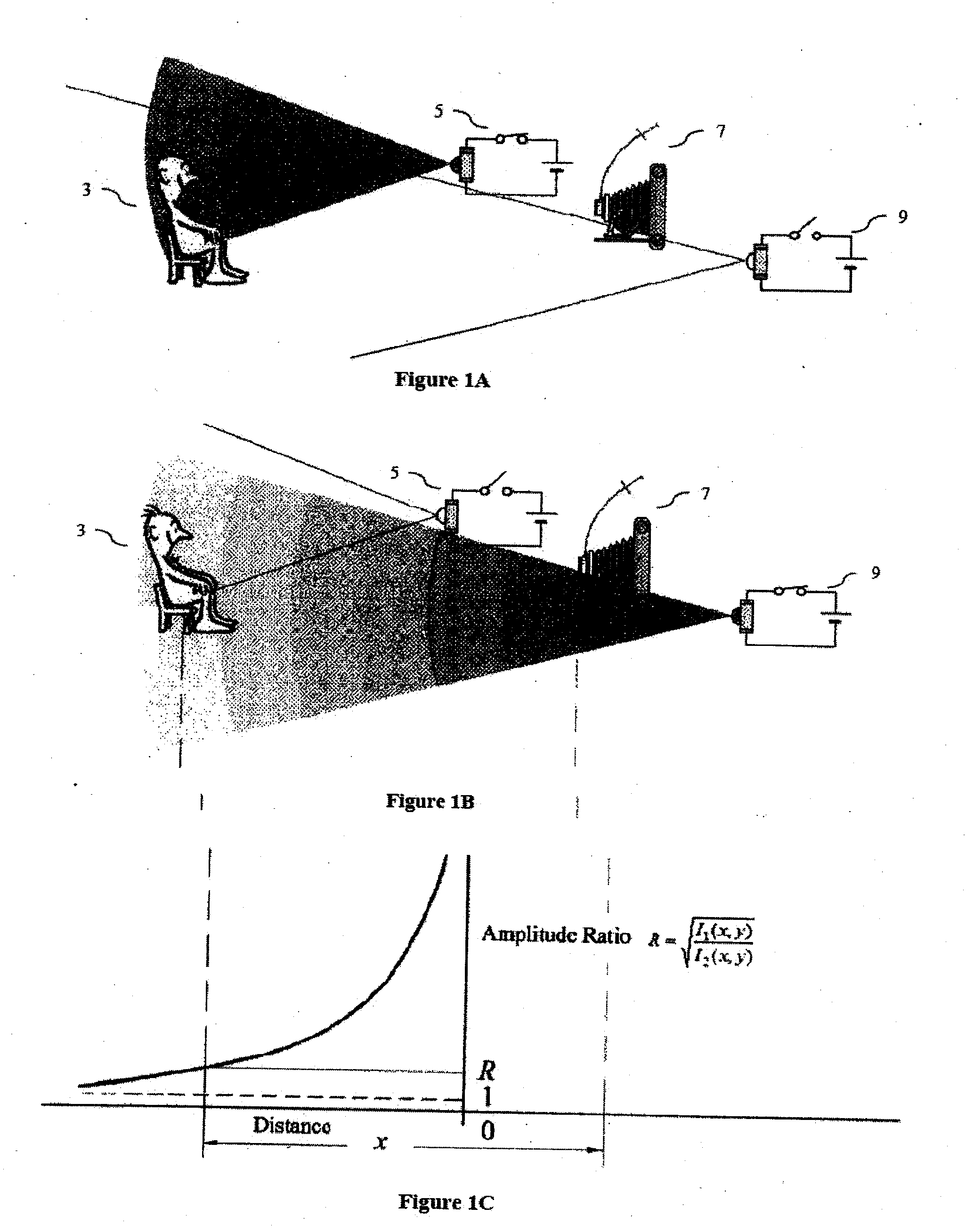
[0025]FIG. 1a illustrates the distance mapping apparatus 1 capturing an image I1 of a target object 3 using a first illuminating device 5 as a light source. The first illuminating device 5 illuminates the target object 3 and the camera device 7 captures an image I1 that is stored by the system on a storage medium (see FIG. 6).

[0026]FIG. 1b illustrates the distance mapping apparatus 1 capturing an image I2 of a target object 3 using a second illuminating device 9 as a light source. The second illuminating device 9 illuminates the target object 3 and the camera device 7 captures an image I2 that is stored by the system on a storage medium (see FIG. 6).

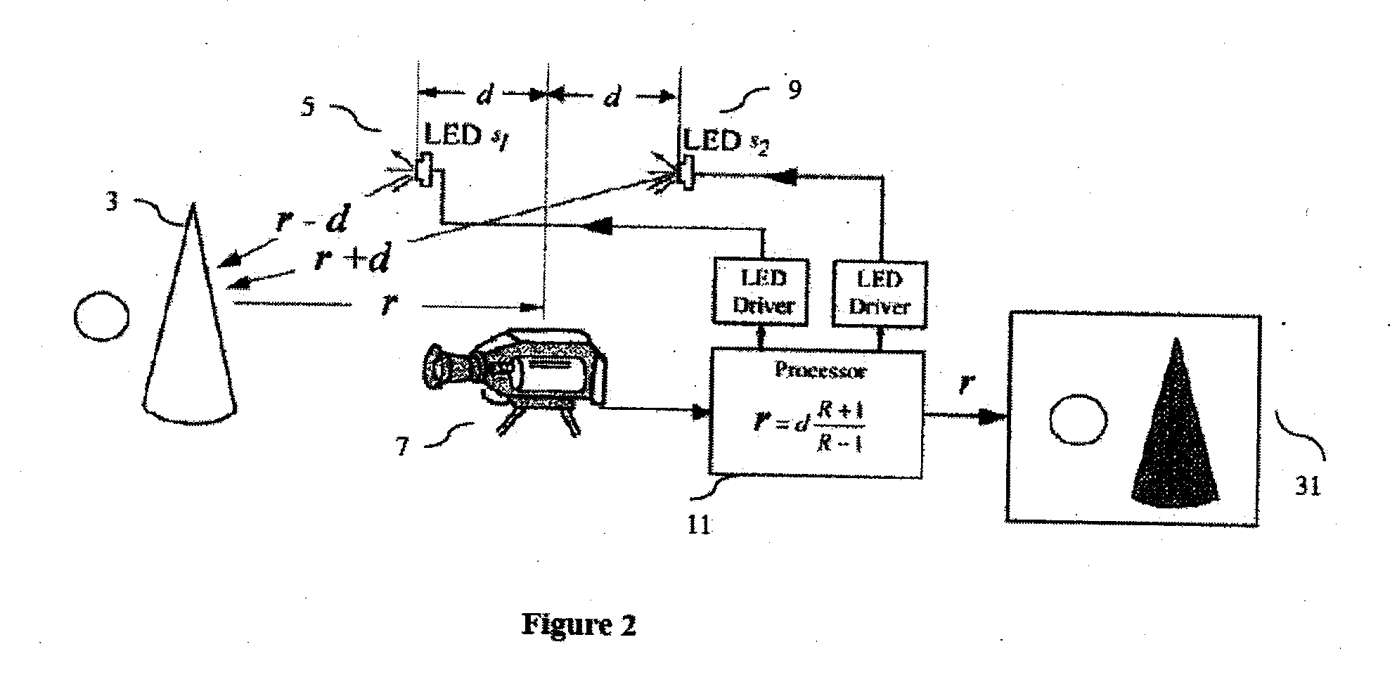
[0027]FIG. 1c illustrates the amplitude ratio between I1 and I2. As further explained (see FIG. 2), through the derivation of the equation to calculate distance, the present invention functions by comparing the relative image intensities between I1 and I2 on a pixel by pixel basis. FIG. 1c demonstrates a graph wherein the relative image ...


PUM


Abstract

The present invention relates to a method and system for detecting and mapping three-dimensional information pertaining to one or more target objects. More particularly, the invention consists of selecting one or more target objects, illuminating the one or more target objects using a first light source and capturing an image of the one or more target objects, then, illuminating the same one or more target objects using a second light source and capturing an image of the one or more target objects and lastly calculating the distance at the midpoint between the two light sources and the one or more target objects based on the decay of intensities of light over distance by analyzing the ratio of the image intensities on a pixel by pixel basis.

Description

[0001]This application claims the benefit of U.S. patent application Ser. No. 11 / 690,503, filed Mar. 23, 2007.FIELD OF THE INVENTION [0002]The present invention relates to a method and system for detecting and mapping three-dimensional information pertaining to an object. In particular, the invention relates to a method and system that makes use of the divergence of light over distance as a means of determining distance.BACKGROUND OF THE INVENTION[0003]Distance mapping or depth mapping cameras have become ubiquitous in numerous fields such as robotics, machine vision for acquiring three-dimensional (3D) information about objects, intelligent transport systems for assisting driver safety and navigation, bioscience for detecting 3D laparoscopic images of internal organs, non-contact fingerprinting, and image manipulation in movie or television studios.[0004]To achieve the goal of distance mapping an object in order to acquire its 3D information, numerous methods have been developed. T...

Claims


Application Information

Patent Timeline
Patent Type & Authority Applications(United States)
IPC IPC(8): H04N13/02H04N5/225G01S17/89
CPCG01S17/08G01S17/89H04N13/254G06T7/586H04N13/207G06T2207/10016
Inventor IIZUKA, KEIGO
Owner IIZUKA KEIGO
Why Eureka
Try Eureka