Apparatus and method for removing self-interference and relay system for the same

a relay system and self-interference technology, applied in the field of relay systems, can solve the problems of repeater also amplifying and transmitting, waste of frequency, and degrading the use efficiency of wireless frequency

Inactive Publication Date: 2010-05-06
LG ERICSSON
View PDF11 Cites 56 Cited by
  • Summary
  • Abstract
  • Description
  • Claims
  • Application Information

AI Technical Summary

Problems solved by technology

Thus, it uses frequency wastefully and degrades the use efficiency of the wireless frequency.
Further, noise on the receiving antenna of the repeater is also amplified and transmitted, and the quality of the received signals deteriorates.
In the case of the ICS repeater, it is difficult to adopt the MIMO scheme, and the efficient improvement of the throughput cannot be anticipated.
However, exact correlation cannot be obtained easily when desired signals or noise components are large.
Thus, the performance of the ICS repeater degrades.
Further, if the SI is not removed completely, the signal may be subjected to an oscillation phenomenon.
However, the latency increases greatly on the system due to the digital signal process required to separate the sections of the transmitting / receiving in time.
Further, there is a problem of lowering frequency efficiency due to the use of the source by the time division.

Method used


Image

  • Apparatus and method for removing self-interference and relay system for the same
  • Apparatus and method for removing self-interference and relay system for the same
  • Apparatus and method for removing self-interference and relay system for the same

Examples


Embodiment Construction

[0031]Hereinafter, preferred embodiments of the present invention will be described in detail with reference to the accompanying drawings. In the following description of the present invention, a detailed description of widely known functions and configurations incorporated herein will be omitted when it may make the subject matter of the present invention rather unclear.

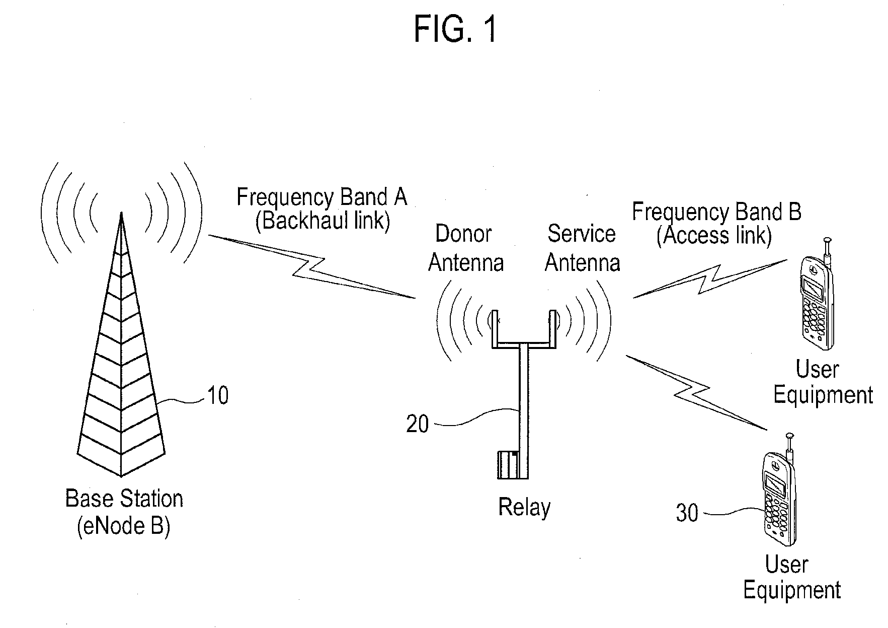
[0032]FIG. 1 shows an exemplary relay system capable of being introduced into the present invention.

[0033]As shown in FIG. 1, relay system 100 may include a base station (eNodeB) 10, relay 20 and user equipment 30 (user equipment, UE). In the present invention, relay 20 may be replaced with a repeater, and frequency band A for a link (Backhaul Link), between base station 10 and relay 20, may be identical to frequency band B for another link (Access Link) between relay 20 and UE 30. That is, relay 20 of the present invention may in some embodiments be an in-band relay where frequency band A and frequency band B are t...


PUM


Abstract

An apparatus, a method and a relay system for removing self-interference (SI). If a relay transmitting end transmits relay-reference signals (R-RS) through a region where a base station does not transmit signals, based on a protocol predetermined with the base station, a relay receiving end obtains SI channel values from signals transmitted by the relay transmitting end and received through a self-interference channel with use of the R-RS, removes the SI from transmitting signals of an uplink or an downlink based on the SI channel values, and relays the SI removed transmitting signals.

Description

[0001]The present application claims priority to Korean Patent Application No. 10-2008-0104358 filed on Oct. 23, 2008, the entire subject matter of which is incorporated herein by reference.BACKGROUND OF THE INVENTION[0002]1. Field of the Invention[0003]The present invention may generally relate to a relay system based on an orthogonal frequency division multiple access (OFDMA) scheme. More particularly, the present invention may relate to an apparatus and a method for removing self-interference (SI) in the relay system by using a relay reference signal (R-RS).[0004]2. Background of the Related Art[0005]International Mobile Telecommunication—Advanced (IMT-Advanced) has been developed to provide multimedia services based on an internet protocol (IP) with data rates of 1 Gbps for fixed or low mobility nodes and 100 Mbps for high mobility nodes. Relay, spectrum aggregation, uplink Multiple-Input and Multiple-Out (MIMO) and interference cancellation between cells are the main technologi...

Claims


Application Information

Patent Timeline
Patent Type & Authority Applications(United States)
IPC IPC(8): H04W72/04
CPCH04B7/15585H04L5/0048H04L27/2691
Inventor CHANG, IL DOO
Owner LG ERICSSON
Why Eureka
Try Eureka