Delay time calculation apparatus and method

a technology of delay time and calculation apparatus, which is applied in the direction of transducer details, stereophonic arrangments, electrical transducers, etc., can solve the problem that the acoustic waves output of these speaker units do not effectively contribute to the formation of the combined wavefront, and achieve the effect of preventing delay tim

Active Publication Date: 2010-05-06
YAMAHA CORP
View PDF0 Cites 6 Cited by
  • Summary
  • Abstract
  • Description
  • Claims
  • Application Information

AI Technical Summary

Benefits of technology

[0012]The present invention provides delay time calculation apparatus and method for delay array type directivity control of a speaker array, which are capable of preventing delay time for some speaker unit of the speaker array from being excessively large, to thereby enable all the speaker units to contribute to formation of a combined wavefront.

Problems solved by technology

As a result, a problem is posed that acoustic waves output from these speaker units do not effectively contribute to the formation of the combined wavefront.

Method used


Image

  • Delay time calculation apparatus and method
  • Delay time calculation apparatus and method
  • Delay time calculation apparatus and method

Examples


first modification

(First Modification)

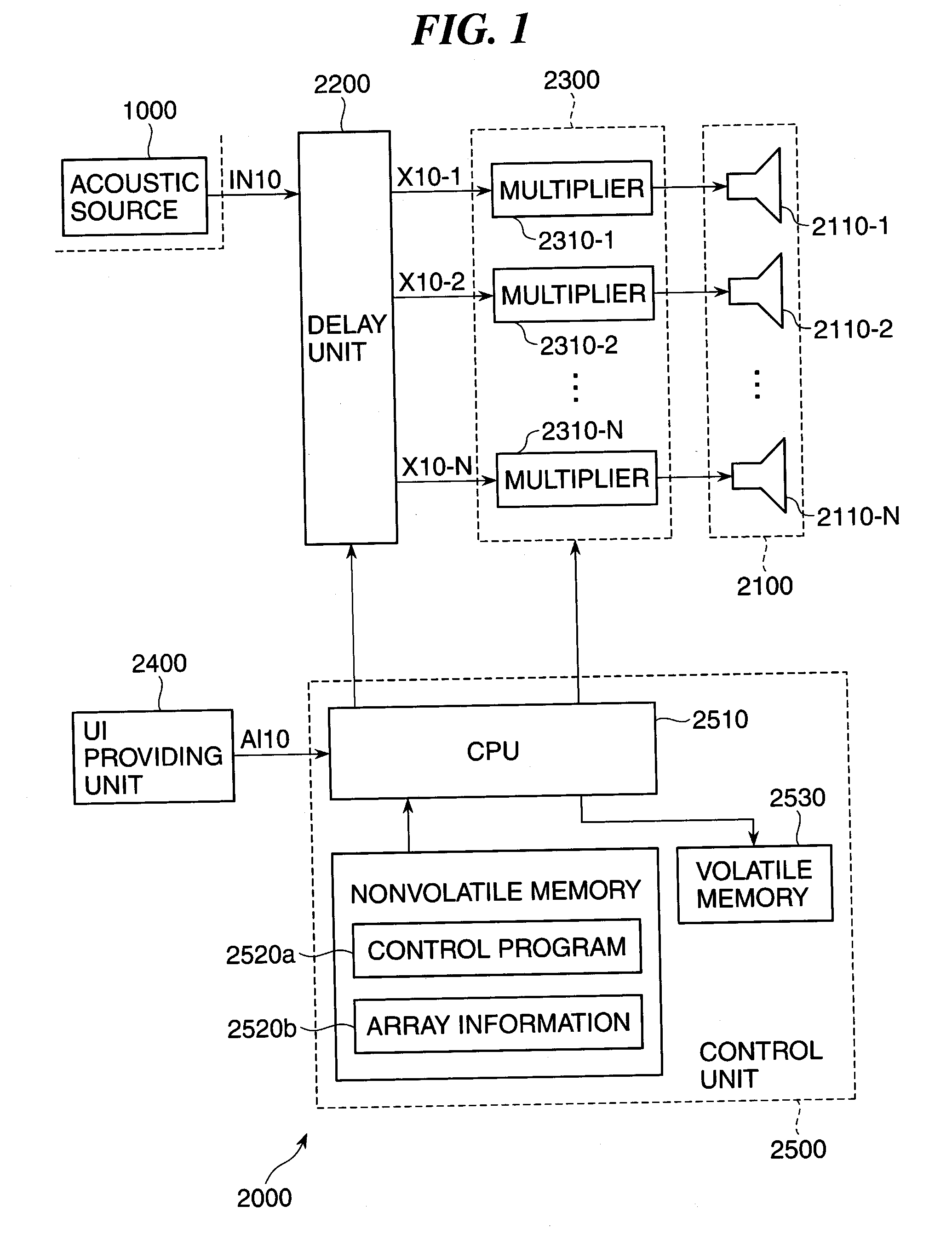
[0065]In the embodiment, this invention is applied to a two-dimensional speaker array in which speaker units are arranged to form a planar baffle surface. However, the speaker array can, of course, be configured to have speaker units arranged to form a curved baffle surface.

second modification

(Second Modification)

[0066]In the embodiment, the rectangular target area is set. However, the target area can have any shape. It is enough to modify or expand or contract the projection image of the array plane obtained by affine transformation such as to cover the target area in just proportion.

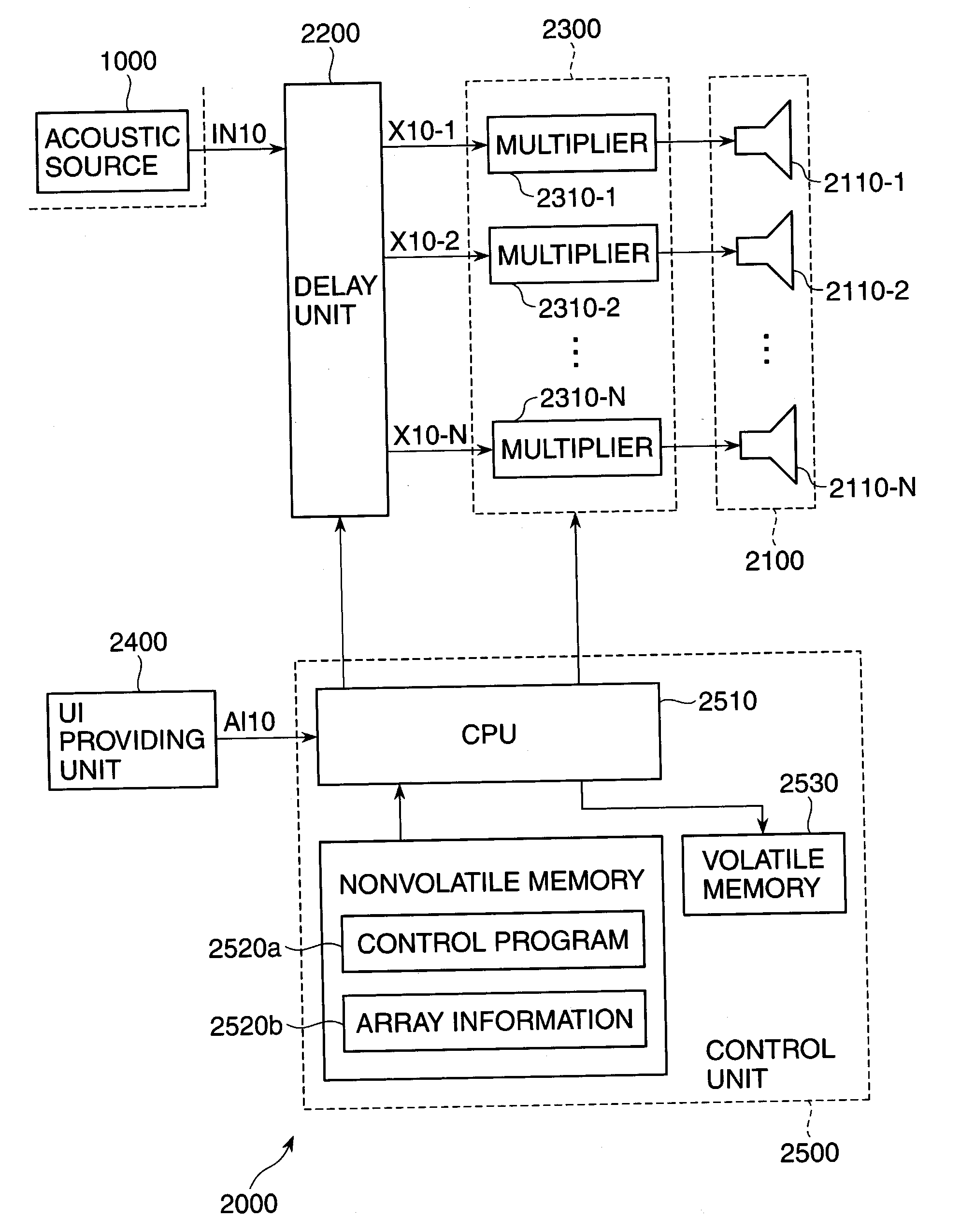
[0067]In the embodiment, the projection image is edited such that projection points of outermost speaker units 2110-i on the array plane of the speaker array 2100 are positioned on the outer periphery of the target area. However, it is enough to implement the edit process such that the projection points of the outermost speaker units 2110-i are not positioned beyond the target area, as shown in FIG. 6A.

[0068]In the edit process of the embodiment, the projection image is expanded or contracted with a constant ratio of expansion and contraction, but the ratio of expansion and contraction is not required to be constant. For example, the ratio of expansion can be smaller toward the center of th...

third modification

(Third Modification)

[0071]In the embodiment, an arithmetic average of differences aji between distances rjj from the speaker units 2110-j to the sound receiving points RP-j and distances rij from the speaker units 2110-i to the sound receiving points RP-j is calculated for each suffix j, an arithmetic average of differences bji between distances rji from the speaker units 2110-j to the sound receiving points RP-i and distances rji from the speaker units 2110-j to the sound receiving points RP-i is calculated for each suffix j, and an average of both the average values is converted into the delay time for the corresponding speaker unit 2110-i. Alternatively, a geometric average or a weighted average of the differences aji and bji can be calculated for each suffix j instead of calculating the arithmetic average thereof, and an arithmetic average, an geometric average, or a weighted average of the geometric averages or weighted averages of the differences aji and bji can be converted i...


PUM


Abstract

A delay time calculation apparatus enabling all the speaker units of a delay array type speaker array to contribute to formation of a combined wavefront. Sound receiving points for acoustic waves output from the speaker units are set within a target area for the acoustic waves. For each speaker unit, an average value of differences between distances between the sound receiving points for the speaker units and other speaker units and distances between the sound receiving points for the speaker units and the speaker units is determined, and an average value of differences between distances from the other speaker units to sound receiving points for the other speaker units and distances from the speaker units to the sound receiving points for the other speaker units is determined. An average of the average values is converted into a delay time, thereby determining the delay time for each speaker unit.

Description

BACKGROUND OF THE INVENTION[0001]1. Field of the Invention[0002]The present invention relates to a technique for controlling directivity of a speaker array comprised of speaker units, and more particularly, to a delay time calculation apparatus and method for achieving directivity control by adjusting differences between delay times in supplying an input audio signal to speaker units.[0003]2. Description of the Related Art[0004]As a speaker array system, a delay array type speaker array system is known (see, for example, Japanese Laid-open Patent Publication No. 2006-211230). In a delay array type speaker array system, delay times of audio signals supplied to speaker units of a speaker array are adjusted for control of directivity of acoustic waves output from the speaker array. The directivity control is to control the propagating direction and the spread of a combined wavefront of acoustic waves output from the speaker units. Delay times are time differences from when an audio sig...

Claims


Application Information

Patent Timeline
Patent Type & Authority Applications(United States)
IPC IPC(8): H04R5/00
CPCH04R1/403H04R3/12H04R2201/401H04R2203/12
Inventor YAMAKAWA, TAKASHIKUSHIDA, KOJI
Owner YAMAHA CORP
Why Eureka
Try Eureka