A multi-probe array microwave imaging system and switch control method

A microwave imaging and switching control module technology, applied in the microwave field, can solve the problems of slow measurement speed and low test efficiency, and achieve the effects of small control delay, high imaging test efficiency, and shortened total test time

Active Publication Date: 2017-04-26
THE 41ST INST OF CHINA ELECTRONICS TECH GRP
View PDF6 Cites 2 Cited by
  • Summary
  • Abstract
  • Description
  • Claims
  • Application Information

AI Technical Summary

Problems solved by technology

[0005] The present invention aims at the disadvantages of slow measurement speed and low test efficiency caused by various delay times such as operating system delay, bus communication delay, and software interruption delay in the conventional switch control software coding implementation method, and proposes a utilization system The multi-probe array microwave imaging system and switch control method triggered by the host trigger pulse signal can achieve the minimum delay waiting time while ensuring the accuracy of the collected data, and achieve the purpose of improving the data collection speed and imaging test efficiency

Method used


Image

  • A multi-probe array microwave imaging system and switch control method
  • A multi-probe array microwave imaging system and switch control method
  • A multi-probe array microwave imaging system and switch control method

Examples


Embodiment Construction

[0046] The following will clearly and completely describe the technical solutions in the embodiments of the present invention with reference to the accompanying drawings in the embodiments of the present invention. Obviously, the described embodiments are only some, not all, embodiments of the present invention. Based on the embodiments of the present invention, all other embodiments obtained by persons of ordinary skill in the art without making creative efforts belong to the protection scope of the present invention.

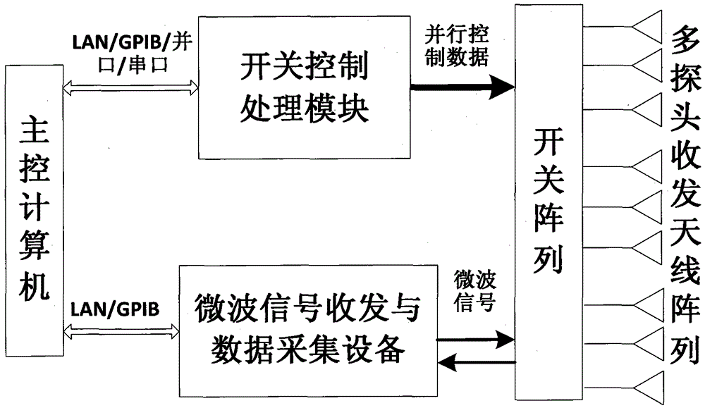
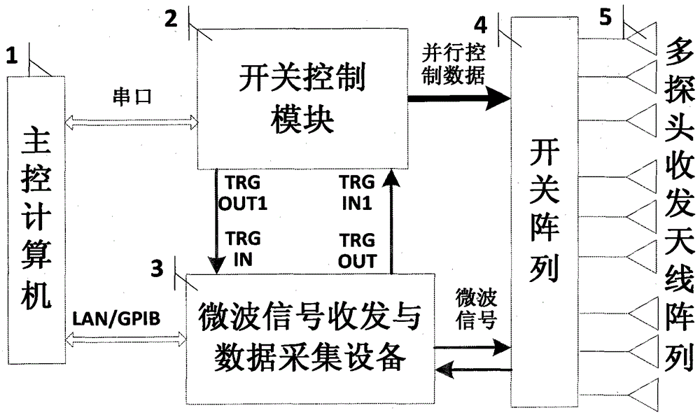
[0047] The invention discloses a multi-probe array microwave imaging system, such as Figure 3a As shown, it includes main control computer 1, microwave signal transceiver and data acquisition equipment 3, switch array 4, multi-probe antenna transceiver array 5, switch control module 2 and other parts, microwave signal transceiver and data acquisition equipment 3 has data acquisition trigger pulse input Output function (for example, vector network analyzers an...


PUM


Abstract

Aiming at the disadvantages of slow measurement speed and low test efficiency due to various delay times such as operating system delay, bus communication delay, and software interrupt delay in the conventional switch control software coding implementation method, the present invention proposes a system using A multi-probe array microwave imaging system and a switch control method for a host triggering a pulse signal, including: a main control computer, a microwave signal transceiver and data acquisition device, a switch array, a multi-probe antenna transceiver array, and a switch control module. In addition to the start command, the entire control The process is realized by the trigger pulse of the hardware, without software intervention, which greatly improves the real-time performance and stability; the use of the hardware pulse signal effectively avoids the operating system delay, bus communication delay, and software interrupt delay in the software coding control process. Various delay times, such as time, realize the minimum delay control in the whole control process.

Description

technical field [0001] The invention relates to the field of microwaves, in particular to a multi-probe array microwave imaging system, and also to a switch control method for the multi-probe array microwave imaging system. Background technique [0002] The multi-probe antenna array microwave imaging system does not require the relative movement between the measured target and the test equipment. It has the advantages of fast test speed, convenient operation, and simple equipment composition. It has become the research and development of microwave imaging, especially in the field of real-time imaging. focus. The multi-probe array microwave imaging system uses a multi-probe array arranged according to certain rules, combined with high-speed electronic switches to switch the transceiver probe antennas to achieve spatial resolution. How to coordinate the switching of the control switch and the data acquisition timing of the host computer not only affects the accuracy of data a...

Claims


Application Information

Patent Timeline
Patent Type & Authority Patents(China)
IPC IPC(8): G01S13/89G01S7/28
CPCG01S7/034G01S13/89
Inventor 常庆功王亚海胡大海唐敬双杜刘革周杨
Owner THE 41ST INST OF CHINA ELECTRONICS TECH GRP
Why Eureka
Try Eureka