Connecting means and method of producing a connection between a first component and a second component

a technology of connecting means and components, applied in the direction of rod connections, large fixed members, furniture joining, etc., can solve the problems of lateral walls of respective components being broken, the process of driving half-fittings into the components along the self-cutting edges is extremely difficult or even completely impossible,

Active Publication Date: 2010-05-06
BAUR FRANZ +2
View PDF11 Cites 16 Cited by
  • Summary
  • Abstract
  • Description
  • Claims
  • Application Information

AI Technical Summary

Benefits of technology

[0007]The object of the present invention is to provide a connecting means of the type mentioned hereinabove which will enable two components consisting of a plurality of materials to be securely connected to one another without giving rise to the danger of damaging the two components during the assembly process.

Problems solved by technology

In the case of hard materials such as a hardwood or metallic materials for example, the process of driving the half-fittings into the components along the self-cutting edges is extremely difficult or even completely impossible.
In addition, there is a danger with the fitting in accordance with DE 196 04 243 C2 that the lateral walls of the respective component could break away when driving-in the half-fittings as a result of the forces arising due to the protruding self-cutting edges.

Method used


Image

  • Connecting means and method of producing a connection between a first component and a second component
  • Connecting means and method of producing a connection between a first component and a second component
  • Connecting means and method of producing a connection between a first component and a second component

Examples


first embodiment

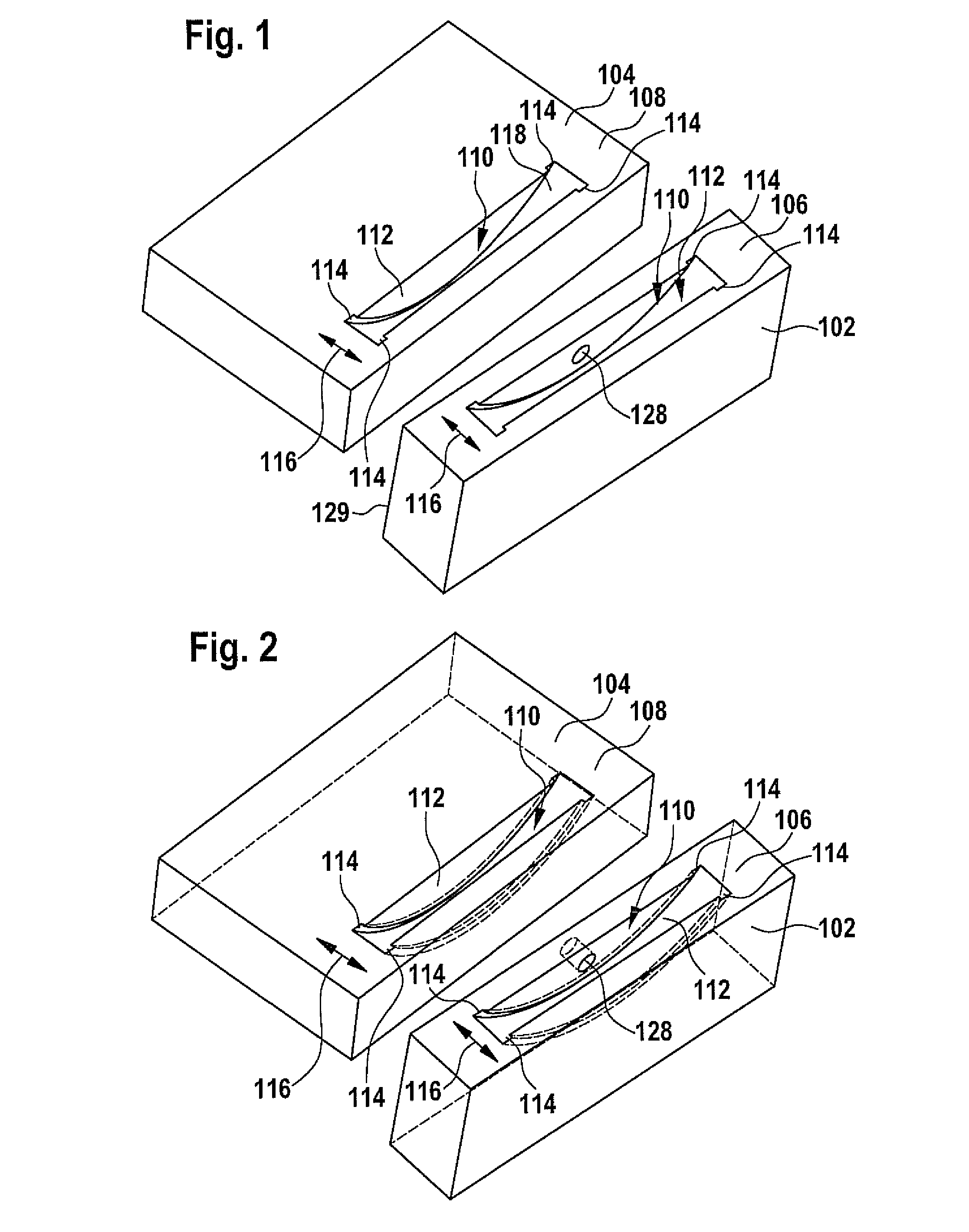
[0138]a connecting means which is illustrated in FIGS. 1 to 9 and bears the general reference 100 is explained in the following using the example of the connection of a first substantially plate-like component 102 to a second likewise substantially plate-like component 104 (see FIGS. 1 to 4).

[0139]The two components 102 and 104 consist for example of wood or plywood, but could consist of any other type of material, for example, of a metallic material or a synthetic material (for example plexiglass). Furthermore, provision may be made for the first component 102 and the second component 104 to consist of materials differing from each other.

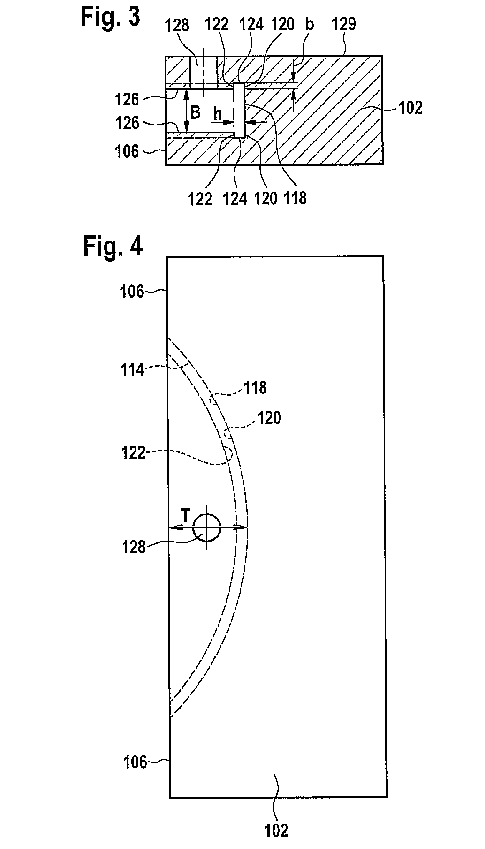
[0140]In the connected state of the two components 102 and 104 which is illustrated in FIG. 7, a contact area 106 forming a narrow side of the first component 102 abuts a contact area 108 of the second component 104 which forms a major face of the plate-like second component 104.

[0141]A respective groove 110, which is formed in the relevant compone...

second embodiment

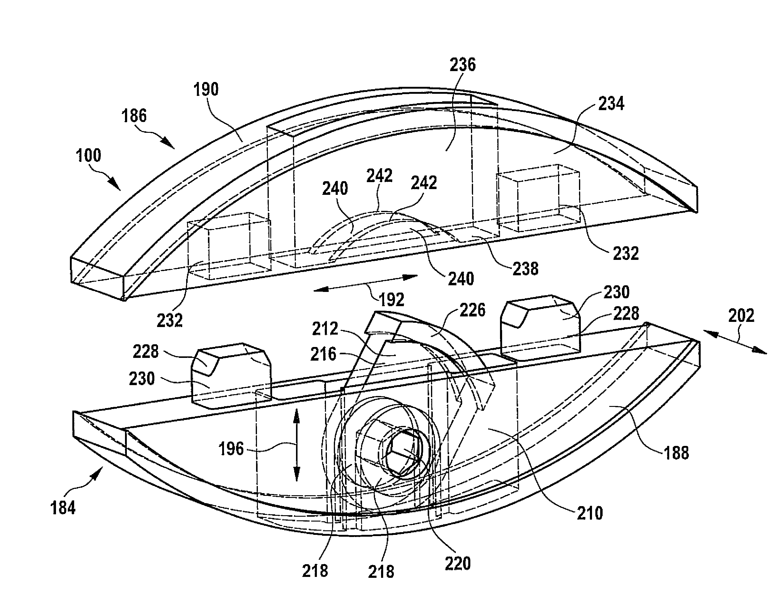
[0237]For the purposes of establishing the connection between the first component 102 and the second component 104, the first connecting element 184 and the second connecting element 186 of the connecting means 100 are inserted into the respective grooves 110 of the first component 102 and the second component 104.

[0238]Then, the second component 104 with the second connecting element 186 is placed on the first component 102 with the first connecting element 184 in such a way that the external thread 248 of the threaded element 246 extends through the access channel 272 of the second connecting element 186 into the seating chamber 250 and comes into engagement with the internal thread 270 of the restraining element 252.

[0239]Subsequently, the threaded element 246 is set into rotation about the rotational axis 268 by means of the (not illustrated) actuating element (a screwdriver for example) which engages in the seating 256 in the head part 254 of the threaded element 246 through an...

third embodiment

[0272]For the purposes of establishing the connection between the first component 102 and the second component 104 by means of the connecting means 100, one proceeds as follows:

[0273]After the first connecting element 184 and the second connecting element 186 have been inserted into the respective grooves 110 of the first component 102 and the second component 104, the second component 104 with the second connecting element 186 is moved against the first component 102 with the first connecting element 184 in such a way that the internal thread 282 of the threaded element 278 comes into engagement with the external thread 314 of the restraining element 316.

[0274]The insertable projections 228 also penetrate the seating pockets 232 of the second connecting element 186 that are complementary thereto and the hump-like raised portion 274 of the first connecting element 184 enters the depression 276 in the second connecting element 186 that is complementary thereto.

[0275]Subsequently, in ...


PUM

PropertyMeasurementUnit
areaaaaaaaaaaa
thicknessaaaaaaaaaa
thicknessaaaaaaaaaa

Abstract

In order to produce a connecting means for connecting a first component and a second component and especially for connecting furniture parts or machine parts which will enable two components consisting of a multiplicity of materials to be securely connected to one another without giving rise to the danger of damaging the two components during the assembly process, wherein the device comprises a first connecting element that it arranged on the first component in the connected state of the components and a second connecting element that is arranged on the second component in the connected state of the components, it is proposed that at least one of the connecting elements should comprise a non self-cutting holding projection which has a curved support surface that is in the form of an arc of a circle in longitudinal section, wherein the holding projection can be inserted into a groove which is provided in one of the components and has a curved undercut surface that is in the form of an arc of a circle in longitudinal section.

Description

RELATED APPLICATION[0001]This application is a continuation application of PCT / EP2008 / 003575 filed May 3, 2008, the entire specification of which is incorporated herein by reference.FIELD OF THE DISCLOSURE[0002]The present invention relates to a connecting means for connecting a first component and a second component, and in particular, for connecting furniture parts or machine parts, comprising[0003]a first connecting element arranged on the first component in the connected state of the components and[0004]a second connecting element arranged on the second component in the connected state of the components.BACKGROUND[0005]Such a connecting means is known from DE 196 04 243 C2 for example.[0006]DE 196 04 243 C2 discloses a fitting for connecting components, said fitting consisting of two half-fittings which are each fixed to a respective one of the components that are to be connected and comprise elements that are adapted to be brought into engagement with one another for establishi...

Claims


Application Information

Patent Timeline
Patent Type & Authority Applications(United States)
IPC IPC(8): F16B7/04F16B12/00B23P11/00B23C3/28B23C1/00
CPCA47B87/002A47B2230/0062B23C5/08B23C5/1054B27F5/023F16B12/2036B23C3/34B23C5/14B23C2220/36B23C2220/40B23C2270/18A47B2230/0077Y10T409/308008Y10T29/49826Y10T409/30784Y10T403/61Y10T407/19Y10T409/307056Y10T403/7009Y10T409/30644Y10T409/3084Y10T403/553Y10T403/59Y10T403/7094Y10T409/306216Y10T409/304424Y10T409/303752Y10T409/306552Y10T409/30672Y10T403/55A47B2230/0059B23C3/30F16B2200/30
Inventor BAUR, FRANZHASER, FRANZSCHNEIDER, WILFRIEDJEKER, PATRICK
Owner BAUR FRANZ
Why Eureka
Try Eureka