Threaded bolt

a technology of threaded bolts and bolts, applied in the direction of screws, nuts, bolts, etc., can solve the problems of complex manufacturing and cost, and achieve the effects of good corrosion resistance, high glass strength, and high retaining valu

Active Publication Date: 2010-05-06
HILTI AG
View PDF29 Cites 7 Cited by
  • Summary
  • Abstract
  • Description
  • Claims
  • Application Information

AI Technical Summary

Benefits of technology

[0007]With the inventive threaded bolt, the manufacturing costs are noticeably reduced, while the robustness of the threaded bolt is retained. When the threaded bolt is driven by a hand-held setting tool, e.g., combustion energy-driven setting tool with a high setting energy of more than 80 Joule, the setting energy is applied to the head of the threaded bolt and therefrom directed to the attachment section through the core region of the load application section, without directing any setting energy to the threaded sleeve.
[0008]Advantageously, the threaded sleeve is injection-molded on the core region. This reduces costs of mounting of a threaded sleeve in comparison with pinning of the threaded sleeve, reducing overall manufacturing costs.
[0010]According to a particular advantageous embodiment of the invention, the threaded sleeve is formed of a glass fiver-reinforced plastic material. Due to a high strength of the glass fiber-reinforced material, high retaining values can be achieved with the inventive threaded bolt.
[0011]It is advantageous, when the head, the core region, and the attachment section are formed of a stainless high-quality steel, which insures good corrosion-resistance.

Problems solved by technology

The threaded bolt is formed of a stainless high-quality steel which makes its manufacturing complicated and cost-intensive.

Method used


Image

  • Threaded bolt
  • Threaded bolt

Examples


Embodiment Construction

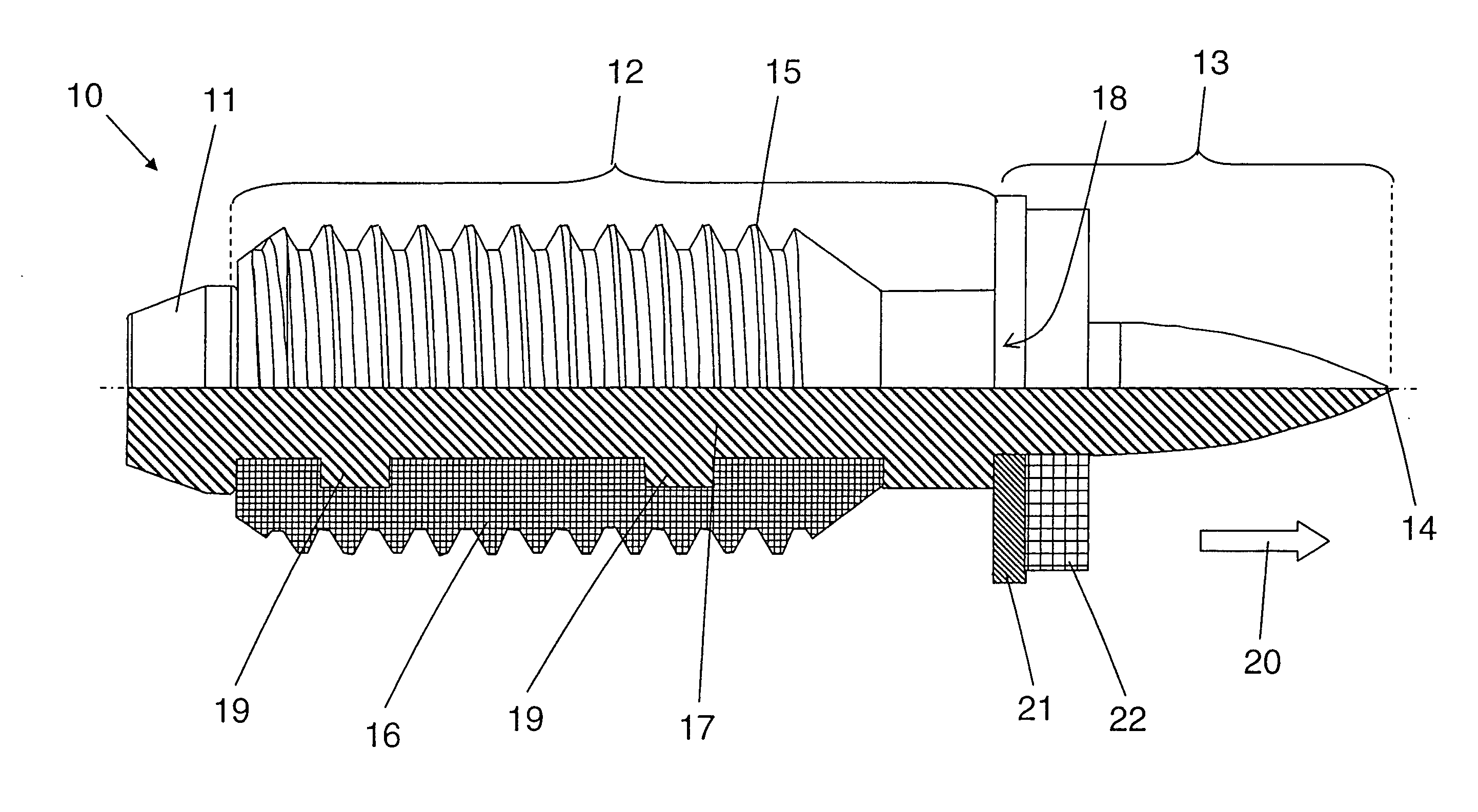
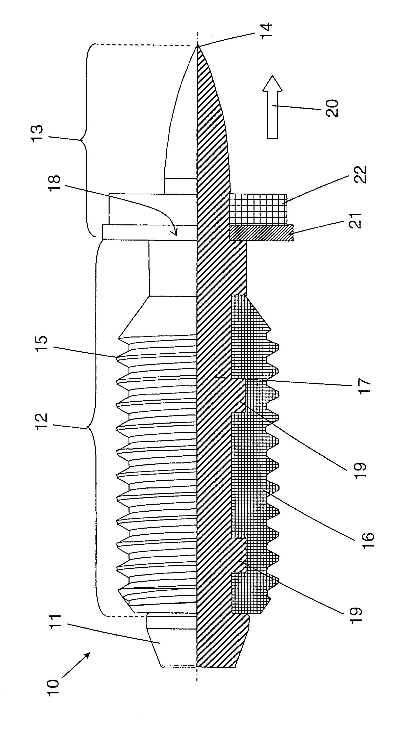
[0015]A threaded bolt 10 according to the present invention has a load application section 12 carrying a thread 15 provided on a threaded sleeve 16 formed of a plastic material. The threaded sleeve 16 is fixedly secured on a bar-shaped core region 17 of the load application section 12. The threaded sleeve 16 is formed, e.g., from a glass fiver-reinforced plastic material and is formed about the core region 17 by a plastic injection-molding process. In order to ensure a fixed mounting of the threaded sleeve 16 on the core region 17, projection-forming elements 19 project from the core region 17 in a radial direction. The projection-forming elements 19 prevent loosening of the material-locking connection between the threaded sleeve 16 and the core region 17 by providing a form-locking connection with the material of the threaded sleeve 16.

[0016]In a setting direction 20 of the threaded bolt 10, an attachment section 13 adjoins the load application section 12. On the free end of the at...


PUM


Abstract

A threaded bolt includes a head (11), a load cation section (12) having a bar-shaped core region (17), an attachment section (13), with the head (11), the core region (17), and the attachment section (13) being formed as a one-piece part formed of metal, and a thread (15)-carrying threaded sleeve (16) formed of a plastic material and secured radially outwardly on the core region (17), with the thread (15) of the threaded sleeve (16) forming the outer thread of the load-application section (12).

Description

BACKGROUND OF THE INVENTION[0001]1. Field of the Invention[0002]The present invention relates to a threaded bolt having a head, a load-application section provided with an outer thread, and an attachment section.[0003]2. Description of the Prior Art[0004]German Utility Model DE 202 09 675 U discloses a threaded bolt having a head, a load application section provided with an outer thread, and an attachment section. The threaded bolt is formed of a stainless high-quality steel which makes its manufacturing complicated and cost-intensive.[0005]The object of the invention is to provide a threaded bolt that can be produced more cost-effectively than the known threaded bolt, without difficulty and that can be driven in a workpiece with a hand-held setting tool.SUMMARY OF THE INVENTION[0006]This and other objects of the present invention, which will become apparent hereinafter, are achieved by providing a threaded bolt the load application section of which has a bar-shaped core region, and...

Claims


Application Information

Patent Timeline
Patent Type & Authority Applications(United States)
IPC IPC(8): F16B35/00
CPCF16B19/14F16B33/06F16B35/041F16B37/068F16B19/086F16B33/006F16B43/00F16B35/00
Inventor BUHRI, REINHARDBOENIG, STEFAN
Owner HILTI AG
Why Eureka
Try Eureka