Foam Pump

Inactive Publication Date: 2010-05-06
TU XUFENG
11 Cites 17 Cited by

AI-Extracted Technical Summary

Problems solved by technology

Foam pump of this structure adopts separated cap and bump body, thus the screw base cannot be too small, leading to large size of the pump.
More over, the spring is provided outside of ...

Method used

[0019]Said pump body 1 is sleeved in a shield 14, the big piston 3 of said head cap 6 is located inside the shield cam ring 141, which sets the upper limit of said big piston 3, part of said shield 14 corresponding to said pump body 1 and said head cap 6 are engaged flexibly to facilitate air inlet. Said shield 14 is further enclosed by a transparent enclosure 23.
[0021]The lower through hole of said piston rod 5 is connected with the small piston base 18, which is sleeved by the small piston 4 at the middle slidingly, said small piston 4 adopts double-valve structure, the lower end of the...

Benefits of technology

[0011]Compared with existing technologies, this invention has the advantages as follows: makes the pump body and the big cover integrated, thus the air cavity can be enlarged, the working pressure of the foam pump can be improved with the big cover of the same size, and the foaming effect of the foam pump can be enhanced; it further integrates the head cap with said big piston, providing se...

Abstract

A foam pump, comprising a pump body (1), a big cover (2), a big piston (3), a small piston (4), a piston rod (5), a head cap (6) and a foam screen (7), featured by that: said pump body (1) is at the upper part, said big cover (2) is at the lower part, said pump body (1) being integrated with said big cover (2), said head cap (6) being integrated with the lower big piston (3); a sealing ring (9) of elastic materials being provided between said big piston (3) and the inner wall of said pump body (1) for tight engagement, which forms an one-way valve structure, which makes the pump body and the big cover integrated, thus the air cavity can be enlarged, the working pressure of the foam pump can be improved with the big cover of the same size, and the foaming effect of the foam pump can be enhanced; said head cap being integrated with said big piston, a sealing ring is provided between said big piston and the inside wall of the pump body, which simplifies the structure of the big piston and makes the internal structure of the foam pump more compact.

Application Domain

Positive displacement pump componentsLiquid transferring devices +4

Technology Topic

Working pressureFoam pump +1

Image

  • Foam Pump
  • Foam Pump
  • Foam Pump

Examples

  • Experimental program(1)

Example

[0015]Detailed description of this invention will now be described with reference to the drawings.
[0016]The embodiment as shown in FIGS. 1-3 is a preferred embodiment of this invention.
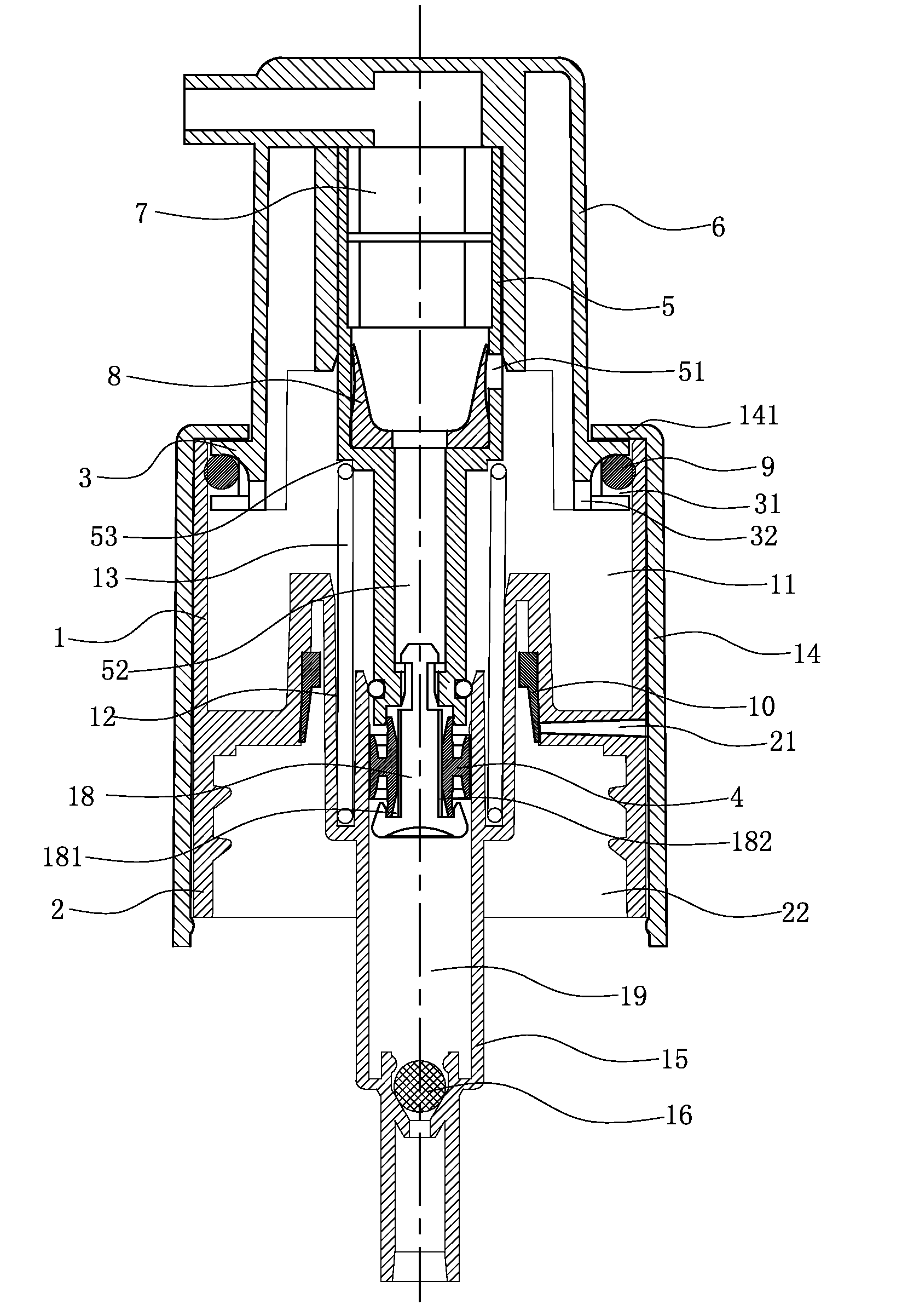
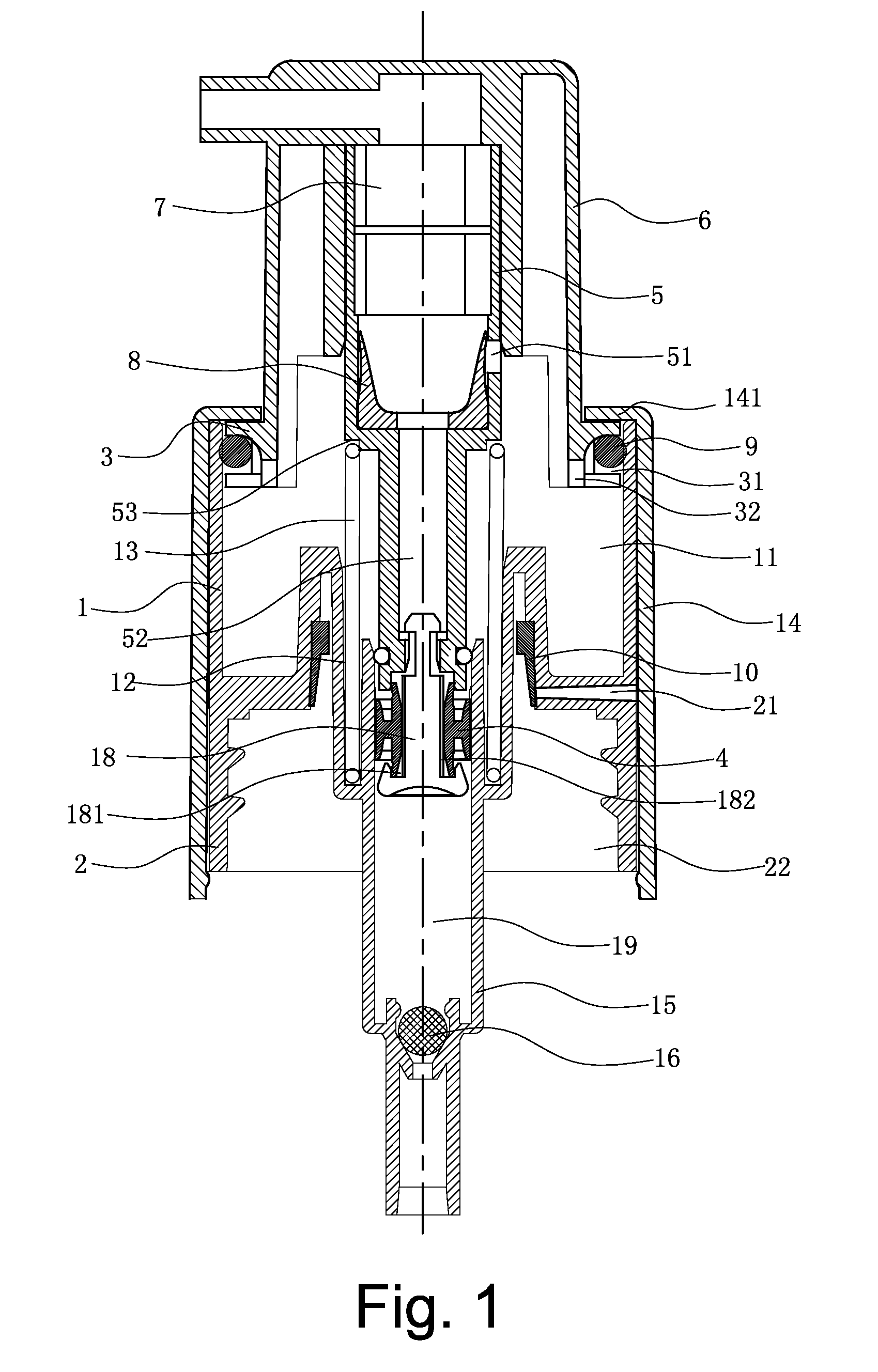
[0017]A foam pump, comprising main parts of the pump body 1, big cover 2, big piston 3, small piston 4, piston rod 5, spring 13, head cap 6 and the foam screen 7; said pump body 1 and big cover 2 being formed into a integral structure, the pump body 1 being the upper part, the big cover 2 being the lower part, the upper part being corresponding to the pump body in the former patent, the lower part functions being corresponding to the big cover in the former patent, an inside thread hole 22 with the screw base diameter of 24-25 mm forming on the lower inside wall of said big cover 2, a sucker 15 being provided at the lower part of pump body 1, a steel bead 16 located inside the upper part of said sucker 15 being engaged with a valve base to form an one-way valve.
[0018]The head cap 6 is integrated with the big piston 3 by a single forming, a sealing ring 9 made of elastic materials is provided between said big piston 3 and the inside wall of said pump body 1, i.e., a circular groove 31 is formed along the circumference of said big piston 3, allowing said sealing ring 9 to slide up and down freely inside said groove 31 easily, which is provided with an air inlets 32 for connection with the outside on the inner lower wall and the bottom, an one-way valve structure is formed with the function of the sealing ring 9 and the air inlet 32 on said circular groove 31.
[0019]Said pump body 1 is sleeved in a shield 14, the big piston 3 of said head cap 6 is located inside the shield cam ring 141, which sets the upper limit of said big piston 3, part of said shield 14 corresponding to said pump body 1 and said head cap 6 are engaged flexibly to facilitate air inlet. Said shield 14 is further enclosed by a transparent enclosure 23.
[0020]A circular groove 12 with a U-shaped section is formed on the lower part of said pump body 1, said piston rod 5 is provided with a shoulder 53 in the middle and is sleeved in a spring 13, which is supported between said circular groove 12 and said shoulder 53.
[0021]The lower through hole of said piston rod 5 is connected with the small piston base 18, which is sleeved by the small piston 4 at the middle slidingly, said small piston 4 adopts double-valve structure, the lower end of the big valve inside it is engaged with the circular groove 181 on said small piston base 18, to facilitate engagement, said circular groove 181 is provided with a tapered surface on the flange. A shallow groove 182 is formed on the surface of said small piston base 18 to connect the liquid cavity 19 below with the air-liquid mixing cavity 52 above.
[0022]An one-way valve is provided between said air-liquid mixing cavity 52 of said piston rod 5 and the air cavity 11 of said pump body, moreover, the main body of the one-way valve adopts valve leaves 8 in the sleeve shape made of elastic materials like silica gel, said valve leaves 8 are provided with staged surfaces for installation on said piston rod 5, besides, the upper parts of said valve leaves 8 become a sealing valve with ascending diameter and a tapered cavity, said through holes 51 are (one or multiple) provided on the piston rod on the side of the sealing surface of the valve, if multiple, the through holes 51 are distributed evenly along the circumference to connect the air-liquid mixing cavity 52 of said piston rod and the air cavity 11. In this way, the sealing surface on the upper end of valve leaves 8 is in tight engagement with the through holes 51 on said piston rod to form the one-way valve structure.
[0023]The air hole 21 is provided on the big cover 2 for connection with the outside through the one-way valve 10 inside the big cover 2, said one-way valve 10 adopts elastic valve and the air hole 21 in tight engagement.
[0024]To provide interval between the shield 14 and the big cover 2 to facilitate the air hole 21 to allow air in, a shallow groove 22 is provided along the circumference of said big cover 2, said air hole 21 is provided in said shallow groove 22.
[0025]The forming screen 7 is limited in the middle to upper part of the piston rod 5, please see the Chinese invention patent under patent No. CN 200720113219.8 for details.
[0026]The head cap 6 is around the piston rod 5 with its lower end telescopically inserted in the pump body 1, and then the big cover 2 is connected with the bottle jack thread of the case of the atomizer to form the container with the foam pump.
[0027]The working principles and operation procedure are as follows.
[0028]When the head cap 6 is pushed, it drives the piston rod 5 to move downwards, the sealing ring 9 on the side of said big piston 3 slides upwards under the friction of the pump body 1, which separates the air cavity 11 inside said pump body 1 from the outside in the sealed state, in the meanwhile, under the driving force of the piston rod 5, the compression air cavity 11 of the big piston 3 indirectly connected with the piston rod 5 is provided with increased air pressure, then the air inside it enters the air-liquid mixing cavity 52 in the piston rod after passing the through holes 51 on the piston rod 5 and pushing the valve leaves 8 open, which drives the mixture of air and liquid to form in the foaming screen 7 and the head cap 6 and then sprayed out from the foaming hole of nozzle of the head cap 6; the piston rod 5 keeps driving the small piston 4 downwards by overcoming the elastic force of the spring 13, due to the resistance between the small piston 4 and the inner wall of the sucker 15, the small piston 4 adopts lagging movement at the beginning and slides relative to the small piston base 18, it is impossible to realize sealing contact between the lower end of the small piston 4 and the circular groove on the small piston base 18, besides, the small piston 4 moves downwards, which increases the pressure inside the liquid cavity 19 in the pump body 1, the steel bead 16 seals the sucker 15, which prevents the liquid below from entering, however, the liquid in the liquid cavity 19 enters the air-liquid mixing cavity 52 in the piston rod 5 after passing the shallow groove 181 on the surface of the small piston base 18 as driven by the airflow and be mixed with the air from the air cavity 11 into the mixture of air and liquid, which is prepared for the next circle.
[0029]When the head cap 6 is released, the piston rod 5 moves upwards under the effect of the spring 13, which drives the piston rod 5 to move upwards, due to the resistance between the small piston 4 and the inner wall of the sucker 15, the small piston 4 adopts lagging movement at the beginning and slides relative to the small piston base 18, a second sealing contact between the lower part of the small piston 4 and the circular groove on the small piston base 18 is realized, besides, the small piston 4 moves upwards, which increases the volume of and decreases the pressure inside the liquid cavity 19 in the pump body 1, it is impossible for the steel bead 16 to seal the sucker 15, in the meanwhile, the air from the outside applies pressure on the atomizer through the air inlet hole 21 on the big cover 2 to make the liquid below enter the liquid cavity 19 while the liquid in the liquid cavity 19 cannot enter the air-liquid mixing cavity 52 in the piston rod 5 through the shallow groove 181 on the surface of the small piston base 18, as driven by the piston rod 5, the big piston 3 also moves upwards, and due to the lagging movement of the sealing ring 9, it slides downwards, which allows the air form outside to compensate the air in the air cavity 11 after passing the interval between the sealing ring 9 and the groove 31 and the air inlet 32 to make preparation for the next cycle; the spraying is realized by circular motions in order.

PUM

no PUM

Description & Claims & Application Information

We can also present the details of the Description, Claims and Application information to help users get a comprehensive understanding of the technical details of the patent, such as background art, summary of invention, brief description of drawings, description of embodiments, and other original content. On the other hand, users can also determine the specific scope of protection of the technology through the list of claims; as well as understand the changes in the life cycle of the technology with the presentation of the patent timeline. Login to view more.

Similar technology patents

Fan Frame of an Axial-Flow Fan

Owner:SUNONWEALTH ELECTRIC MACHINE IND

Electrical connection socket

ActiveUS20140017951A1simplify structuredecrease manufacturing cost
Owner:KIWI INTELLECTUAL ASSETS CORP

Method for operating a drive train

InactiveUS20130060411A1simplify structureshorten shift time
Owner:ZF FRIEDRICHSHAFEN AG

Classification and recommendation of technical efficacy words

  • simplify structure

Dust collecting device for vacuum cleaner

Owner:SAMSUNG GWANGJU ELECTRONICS CO LTD

Medium conveyance device and image formation apparatus

ActiveUS20140210162A1simplify structuresufficient press force
Owner:OKI ELECTRIC IND CO LTD

Aircraft starter generator

Owner:KAWASAKI HEAVY IND LTD

Battery module

ActiveUS20160233465A1simplify structurereduce volume and weight
Owner:LG ENERGY SOLUTION LTD

Linear compressor

InactiveUS20060091735A1simplify structurereduce number of part
Owner:LG ELECTRONICS INC
Why Eureka
Try Eureka