
Eb/sm splitter heat recovery

a heat recovery and splitter technology, applied in the field of low temperature heat recovery techniques, can solve the problems of prohibitively high compression cost and 200 mmhg

Inactive Publication Date: 2010-05-06
STONE & WEBSTER PROCESS TECH
View PDF14 Cites 7 Cited by
  • Summary
  • Abstract
  • Description
  • Claims
  • Application Information

AI Technical Summary

Benefits of technology

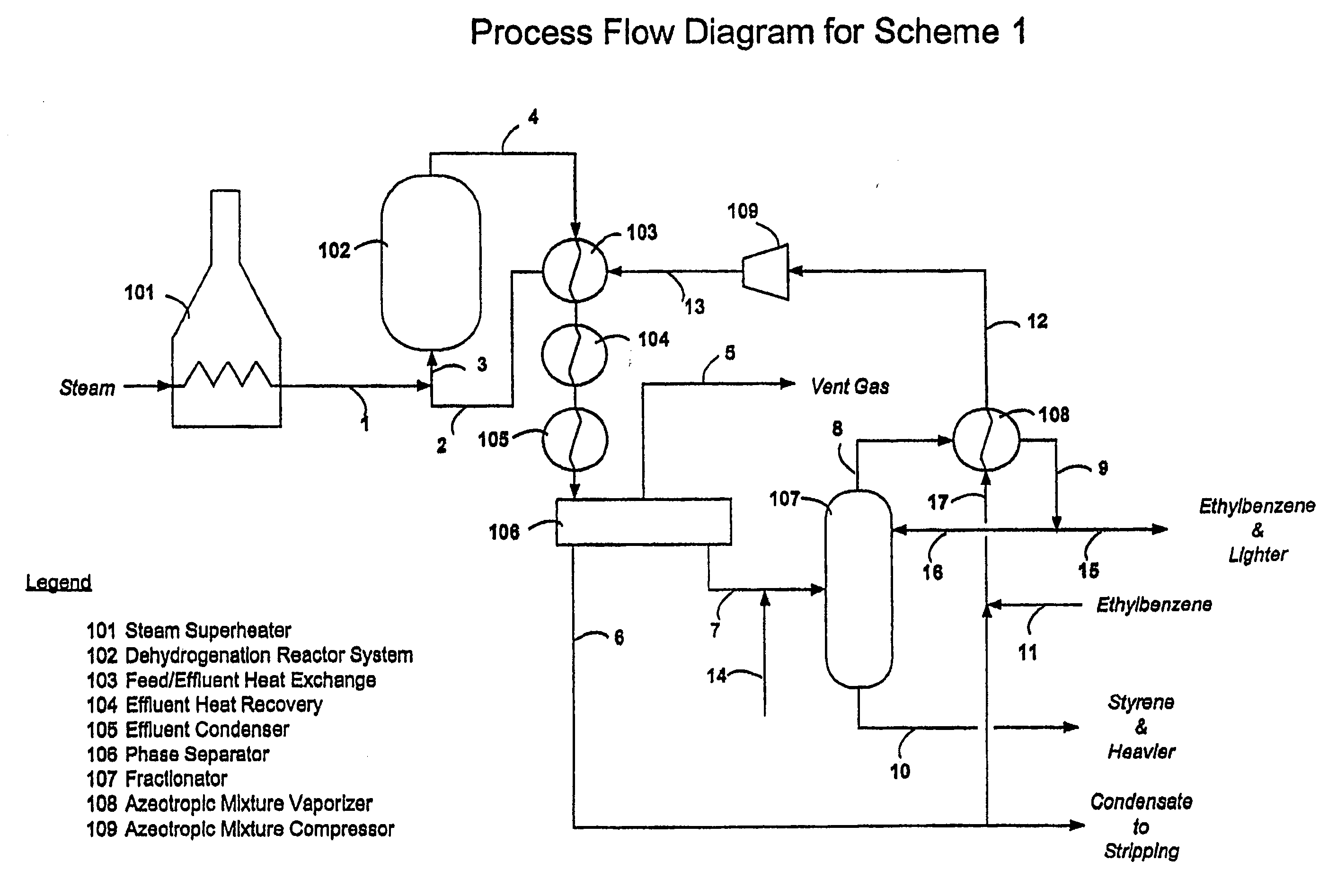
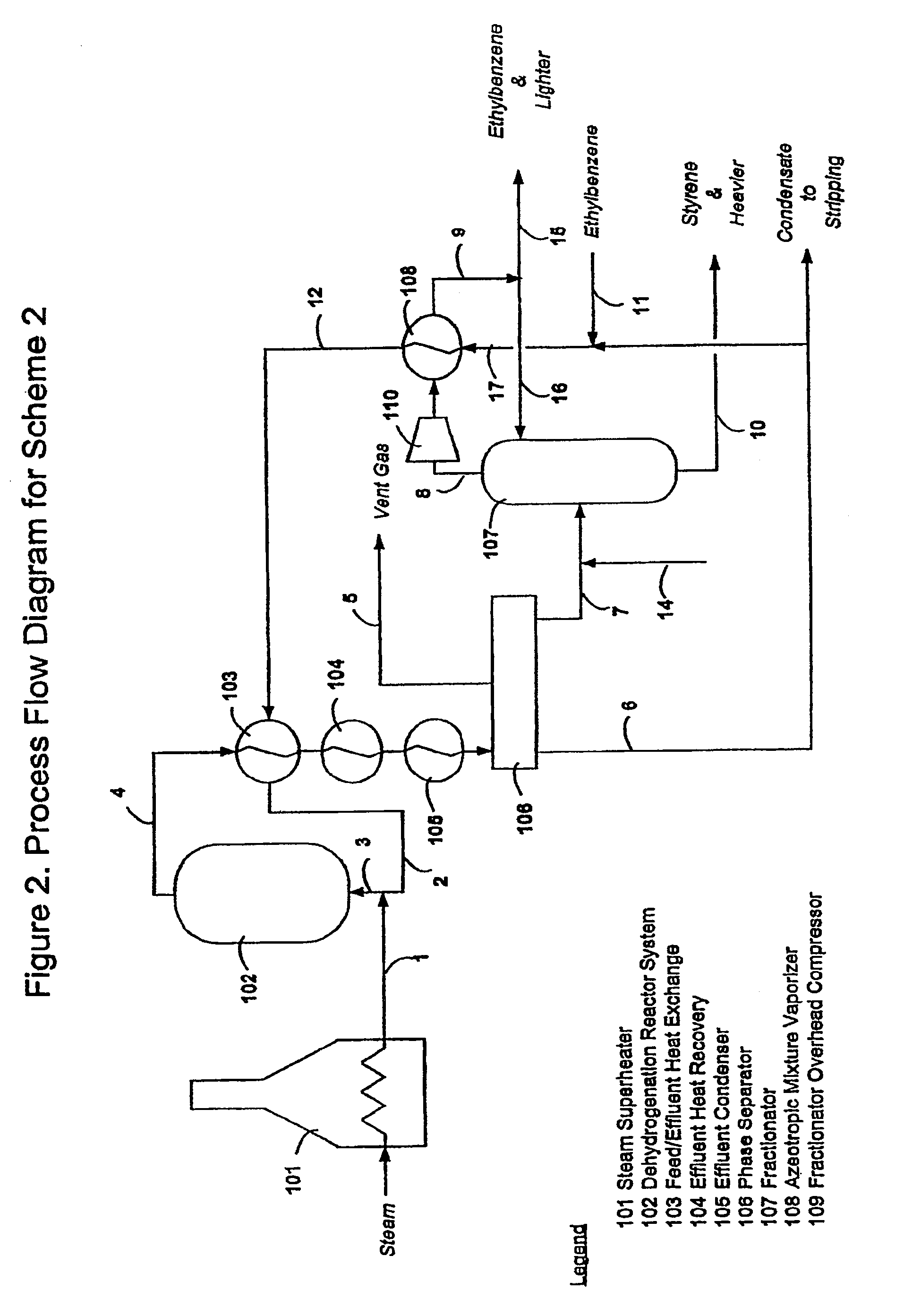
[0008]In a principal embodiment of the new invention described herein, it has been found that the aforementioned limitations of the method taught by U.S. Pat. No. 4,628,136 can be overcome by use of a compressor. Using a compressor at one or more selected locations in the process flow scheme realizes a number of important and unexpected benefits over the prior art including: a) it allows the EB / SM splitter to operate at a substantially lower pressure and temperature; b) it compensates for any reasonable pressure drop increases in the reaction section; c) it allows the EB / SM splitter operating conditions to be set independently from the reaction section of the overall process; d) it allows higher differential temperatures between the condensing overhead and the vaporizing azeotrope, resulting in smaller heat transfer area requirements; and e) it allows recovery of substantially all of the usable heat contained in the overhead stream.
[0010]Thus, the unique features of the methods and apparatus of the present invention allow the azeotropic vaporization of the EB / water mixture to take place in the pressure range of about 150 to 600 mmHg, preferably a range of about 250 to 390 mmHg, which largely falls outside the acceptable pressure ranges taught by prior art methods. In addition, other unexpected efficiencies and economies are realized with the methods and apparatus of this invention as described hereinafter.

Problems solved by technology

Pressures higher than this are undesirable because of the need to operate the dehydrogenation reactors at a higher pressure (requiring more catalyst and more steam to maintain catalyst stability), while operating the system at pressures lower than 200 mmHg makes compression costs prohibitively expensive.

Method used


Image

  • Eb/sm splitter heat recovery
  • Eb/sm splitter heat recovery
  • Eb/sm splitter heat recovery

Examples


Embodiment Construction

[0015]The methods and apparatus of this invention pertain to catalyzed hydrocarbon dehydrogenation processes, for example the process of manufacturing styrene via dehydrogenation of ethylbenzene in the presence of steam at elevated temperatures in a reactor system typically containing an iron oxide based dehydrogenation catalyst.

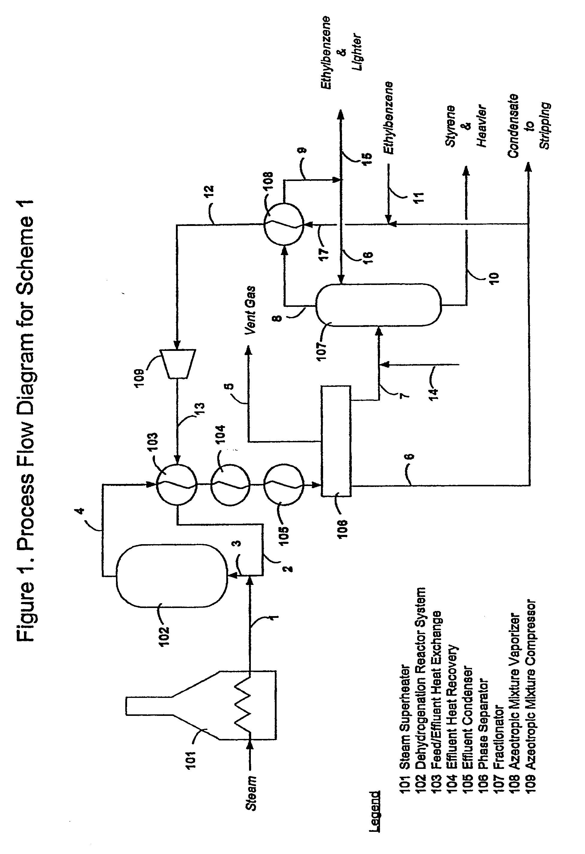
[0016]A first embodiment of this invention, as applied to the manufacture of styrene by the above process, is illustrated in FIG. 1. In this embodiment, a gaseous mixture 2 of ethylbenzene and steam is mixed with additional steam 1 which has been preheated to a temperature of typically between about 700 and 900° C. in a fired steam superheater 101. The resulting mixture 3 is passed through a dehydrogenation system 102 comprising one or more dehydrogenation reactors together with a means of supplying heat to compensate for heat lost due to the endothermic nature of the dehydrogenation reaction. The reactors can be either isothermal or adiabatic, and the heat ...


PUM

PropertyMeasurementUnit
temperatureaaaaaaaaaa
pressureaaaaaaaaaa

Abstract

Improved methods and related apparatus are disclosed for efficiently recovering the heat of condensation from overhead vapor produced during separation of various components of dehydrogenation reaction effluent, particularly in ethylbenzene-to-styrene operations, by the use of at least a compressor to facilitate azeotropic vaporization of an ethylbenzene and water mixture within a preferred range of pressure / temperature conditions so as to minimize undesired polymerization reactions.

Description

CROSS-REFERENCE TO RELATED APPLICATIONS[0001]This application is a divisional application of application Ser. No. 10 / 517,734, filed Dec. 8, 2004, which is a 371 of PCT / US03 / 17944, filed Jun. 5, 2003, which claims benefit of U.S. Provisional Patent Application Ser. No. 60 / 388,091, filed Jun. 12, 2002.FIELD OF THE INVENTION[0002]The present invention relates to a low temperature heat recovery technique in the process of making styrene through dehydrogenation of ethyl benzene at elevated temperatures in the presence of steam. Specifically, this invention teaches methods of recovering the heat of condensation from the overhead vapor leaving the distillation column which is used for separation of unreacted ethylbenzene from the styrene product (hereinafter referred to as the EB / SM splitter) together with related apparatus. Typically, this heat is rejected to atmosphere through the use of cooling water or air fins and is therefore wasted. The EB / SM splitter typically has a heat removal re...

Claims


Application Information

Patent Timeline
Patent Type & Authority Applications(United States)
IPC IPC(8): B01J8/00B01D5/00C08K5/01C07C7/06B01B1/00B01D1/28B01D3/14B01J10/00C07C2/64C07C5/333C07C7/04C07C15/46
CPCB01B1/005B01D1/28B01D3/14C07C5/3332Y02P20/123C07C7/04Y02P20/51Y02P20/57Y02P70/34C07C15/46Y02P70/10C07C5/367C07C5/333Y02P20/10Y02P20/50
Inventor OLEKSY, SLAWOMIR A.WELCH, VINCENT A.WHITTLE, LESLIE F.
Owner STONE & WEBSTER PROCESS TECH
Learn More