Vibrating Massage Roller Utilizing a Plurality of Supports and Eccentric Weights

a massage roller and eccentric weight technology, applied in the field of massage rollers, can solve the problems of prior art solutions that use eccentric weights rotating about axels and fail to evenly distribute vibrations to rollers or other massager surfaces, and achieve the effect of minimizing vibrational attrition and maximizing efficiency

Active Publication Date: 2010-05-06
HEALTH E VIBRATIONS
View PDF43 Cites 17 Cited by
  • Summary
  • Abstract
  • Description
  • Claims
  • Application Information

AI Technical Summary

Benefits of technology

[0010]To accomplish these objectives, the vibrational roller comprises a motor with an axle extending cantileverally therefrom with a plurality of eccentrically positioned weights and a plurality of supports that are so positioned that they are of different distances from the motor. Two cooperative motors may be positioned so as to both operate the axle. The motors are controllable to selectively alter vibrational characteristics, such as frequency and amplitude. The weights are positioned and synchronized to maximize efficiency and minimize vibrational attrition. In use, the roller also comprises a durable casing with a deformable outer shell (permanent padding) and utilizes selectable padded covers, into which the roller may be inserted so as to vary resistance, pressure, texture, vibrational transmission, and other factors.

Problems solved by technology

The drawback is that such vibrating rollers are constructed with a motor and eccentric weight system along the cylindrical axis.
So if the weight is at one end of the roller, vibrations will dissipate as they travel the length of the roller.
This is problematic if the motor is inaccessible for repair, especially when the motors are totally encased in a support material.
Prior art solutions that use eccentric weights rotating about an axel fail to evenly distribute vibrations to a roller or other massager surface as they generally have only two contact points, one at the motor and one at or by a terminal end of the axel.
This localizes all vibrational transmission at those two end points and can cause “weak spots” or “dead zones” along the length of a massager apparatus, especially if they are improperly spaced and allow destructive interference between the two points of contact.

Method used


Image

  • Vibrating Massage Roller Utilizing a Plurality of Supports and Eccentric Weights
  • Vibrating Massage Roller Utilizing a Plurality of Supports and Eccentric Weights
  • Vibrating Massage Roller Utilizing a Plurality of Supports and Eccentric Weights

Examples


Embodiment Construction

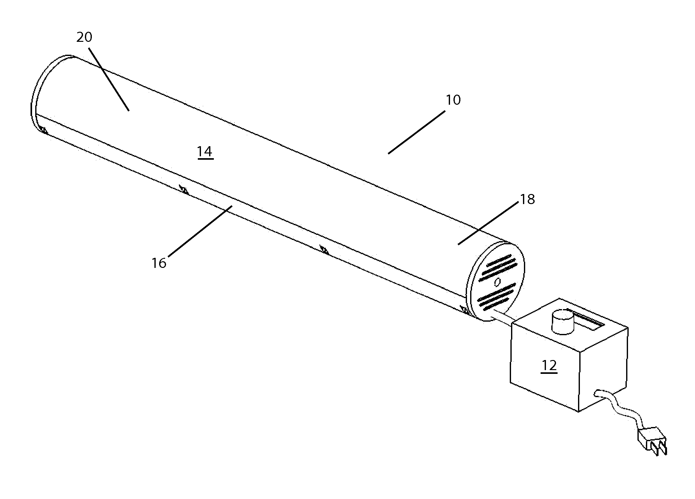
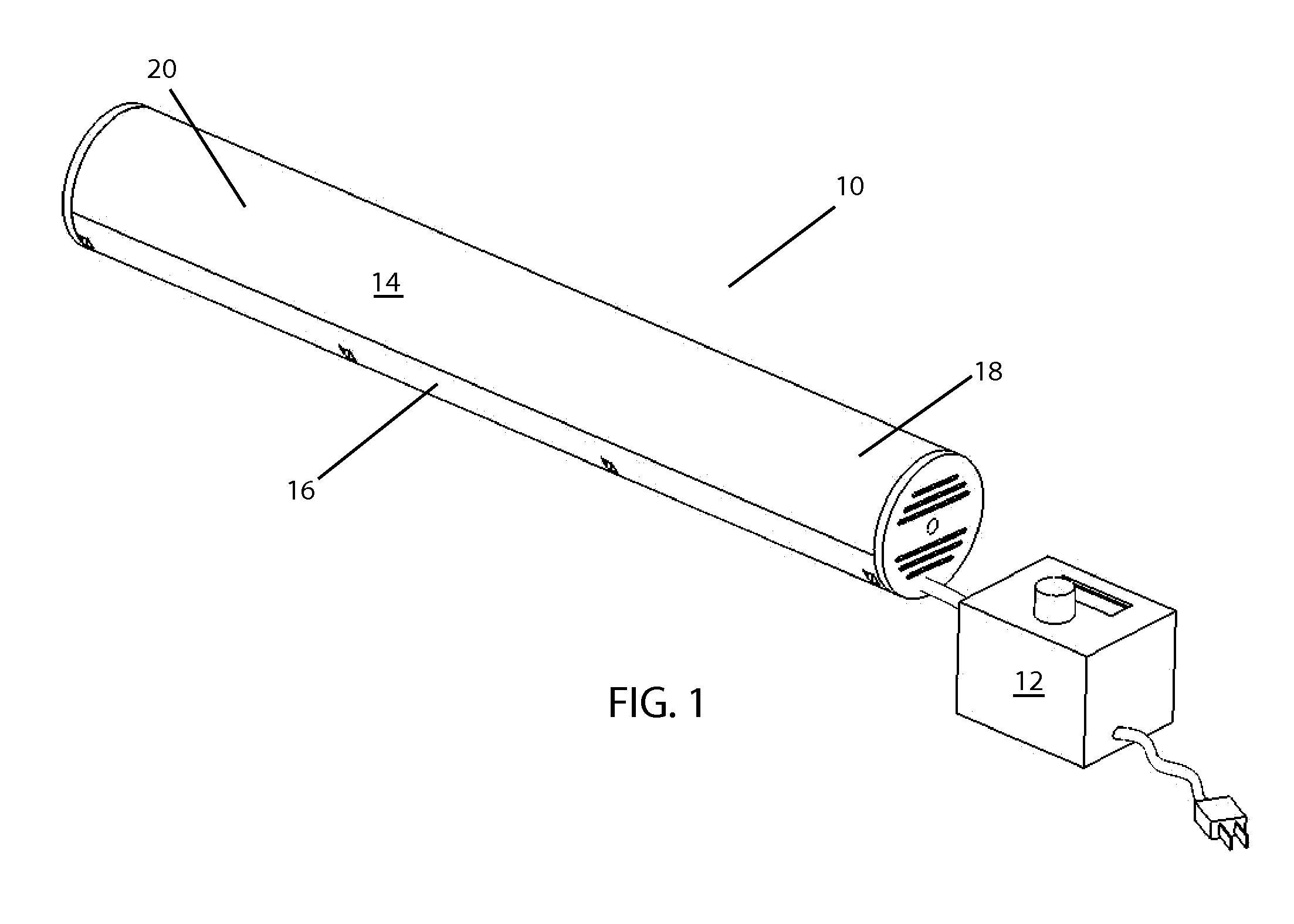
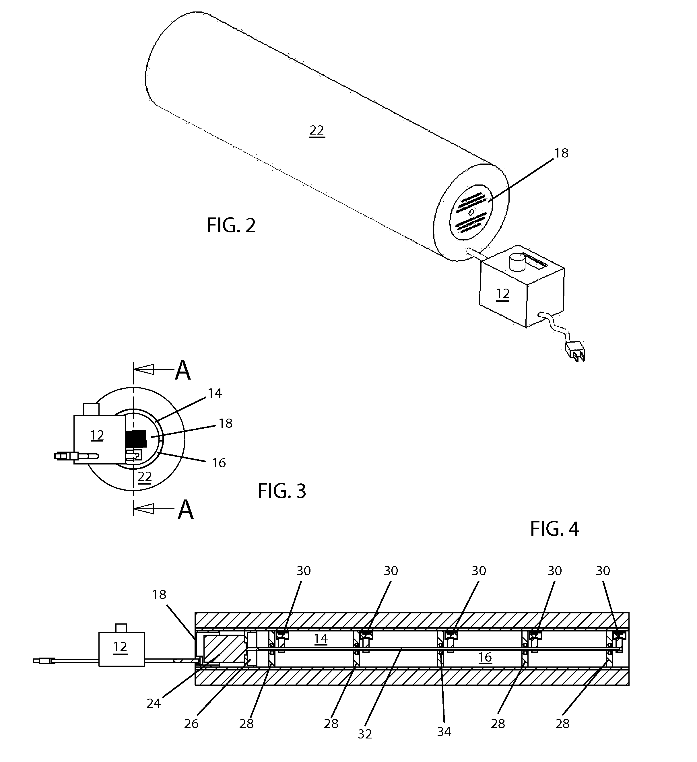
[0023]With reference now to the drawing, the preferred embodiment of the vibrational roller is herein described. It should be noted that the articles “a”, “an”, and “the”, as used in this specification, include plural referents unless the content clearly dictates otherwise.

[0024]In its basic construction, shown in FIGS. 1-6, the vibrational roller 10 comprises a tubular casing 14, 16 with a hollow center. Resident inside the center, is a shaft (or “axle”) 32 mounted between a thrust bearing and a motor 24. A coupling may be used to couple the shaft 32 to the motor 24 or the shaft 32 may connect directly to the motor 24 as shown in the figures. Supports 28 are provided to provide linkage between the casing 14, 16 and the shaft 32. Bearings 34 provide a rolling surface, and thus reduced friction, to the shaft 32. A plurality of eccentric weights 30 are positioned along the shaft 32. These weights 30 are each a different length from the motor 24, or from a chosen reference point that i...


PUM


Abstract

The present invention is a vibrational roller utilizing a motorized vibrational drive using a plurality of eccentric weights and associated supports. The weights are positioned along the axis of rotation in a manner to synchronize them and minimize vibrational dissipation throughout the roller. Each weight has at least one associated support. The supports then transmit vibrational forces to the surface of the roller in an evenly distributed manner. A second co-operational motor may be used to extend motor life and aid in initiating vibrations. A control panel and associated circuitry are utilized to alter vibrational characteristics. The roller may be battery powered or powered through a standard wall outlet. The roller itself is manufactured of a durable yet deformable material, such as foam rubber, and may be inserted into selectable sleeves of varying physical properties for desired effect.

Description

CROSS-REFERENCES TO RELATED APPLICATIONS[0001]The present Application claims priority as a non-provisional perfection of prior filed U.S. Provisional Application 61 / 111,961, filed Nov. 6, 2008 and incorporates the same by reference herein it its entirety.FIELD OF THE INVENTION[0002]The present invention relates to the field of massagers and more particularly relates to a massage roller that utilizes a plurality of eccentric weights rotating at different points along the same axis throughout the length of the roller and an associate plurality of vibrational transmission supports.BACKGROUND OF THE INVENTION[0003]Massage is the manipulation of a person's muscles in order to effect a release of muscular tension. It involves many strategies, including kneading and stretching muscles, percussive striking, and vibration. Massage is well known in the fields of medicine, chiropractic, physical therapy and kinesiotherapy. In fact, massage is its own field of practice, requiring study and, in ...

Claims


Application Information

Patent Timeline
Patent Type & Authority Applications(United States)
IPC IPC(8): A61H1/00
CPCA61H15/0078A61H2015/0014A61H2015/0071A61H2023/0272A61H2023/0281A61H2201/5043
Inventor GODFREY, BRIAN P.WARNER, VINCE
Owner HEALTH E VIBRATIONS
Why Eureka
Try Eureka