
Dewatering system

a technology of return drilling and dewatering system, which is applied in the direction of multi-stage water/sewage treatment, other chemical processes, borehole/well accessories, etc., can solve the problems of limited shelf life, reducing the effective life of polymers, and hygroscopic polymers

Active Publication Date: 2010-05-13
MI
View PDF8 Cites 22 Cited by
  • Summary
  • Abstract
  • Description
  • Claims
  • Application Information

AI Technical Summary

Problems solved by technology

Additionally, these polymers tend to be hygroscopic, and as such, have a limited shelf life.
Thus, when housed in outdoor storage facilities, such as typically occurs in current commercial drilling operations, the hygroscopic polymers take on water from the environment, thereby decreasing their effective life.
Also, the polymers in current commercial systems are typically exposed to wide temperature variations, further resulting in decreased effective life.
Due to the need of polymer solution aging, batch mixing, and the limited shelf life in current commercial systems, management of dry flocculant dewatering systems is costly and resource dependent.
However, due to their nanoemulsion formulation, these products require high energy for emulsion breaking and activation.
Also, the liquid flocculants and coagulants still experience decreased shelf life when exposed to moisture and wide temperature variation.
Thus, the liquid flocculants and coagulants do not always work effectively in current commercial systems.

Method used


Image

  • Dewatering system
  • Dewatering system
  • Dewatering system

Examples


Embodiment Construction

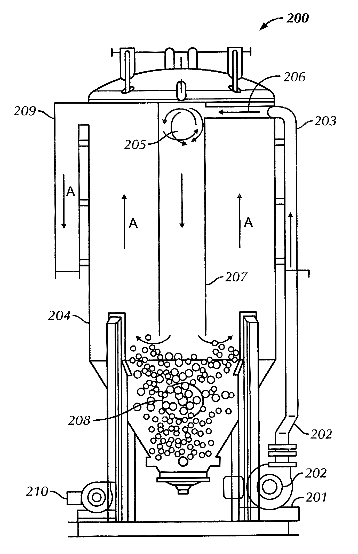
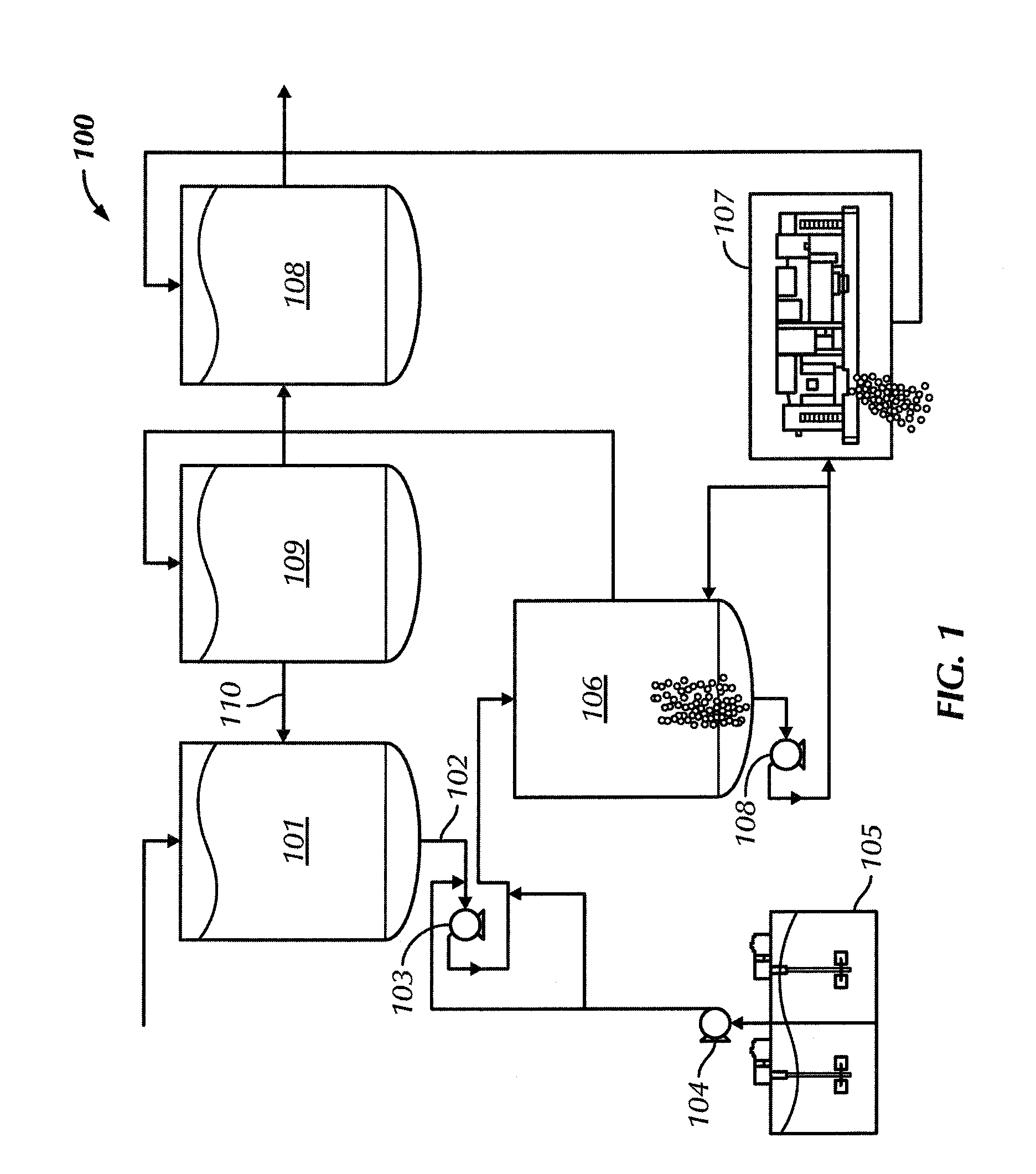
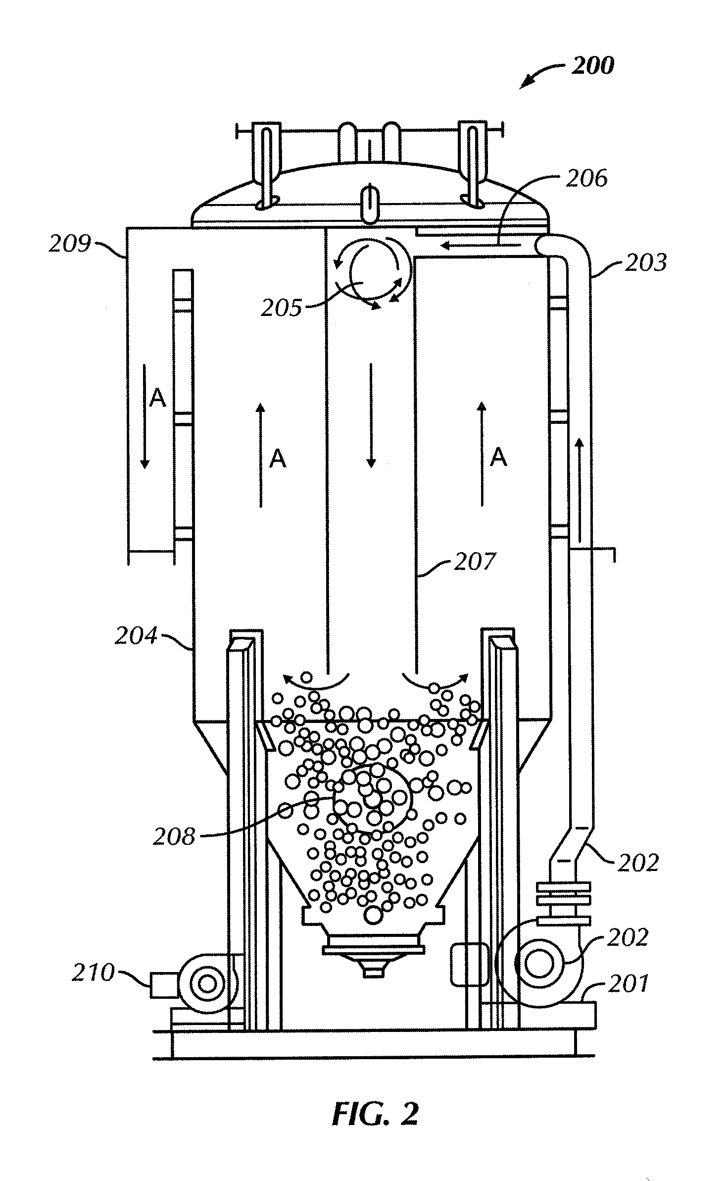
[0016]In one aspect, embodiments disclosed herein relate generally to systems and methods of dewatering return drilling mud at a drilling location. More specifically, embodiments disclosed here relate to systems and methods of dewatering return drilling mud, including a sand trap, at a drilling location.

[0017]Dewatering refers to the removal of solids from a fluid, such that the removed fluids may be reused in various aspects of the drilling operation. Dewatering may be divided into two types of operations, a first operation, total dewatering, which refers to the removal of a maximum quantity of solids from a fluid, resulting in water that may be reused to build new fluids; and a second operation, partial dewatering, which refers to a process used to remove a majority of low gravity solids (“LGS”) from a fluid, such that the fluid may be reused or disposed. Variations of the system disclosed herein may be used for both total and partial dewatering operations. After the fluid is dewa...


PUM


Abstract

A system for processing drilling mud, the system including a primary separation tank having an inlet for receiving drilling waste and an outlet in fluid communication with a feed line, and an injection pump in fluid communication with a polymer tank and the feed line. The system also includes a clarifying tank in fluid communication with the feed line and a first collection tank, wherein effluent from the clarifying tank is discharged into the first collection tank, and a centrifuge in fluid communication with the clarifying tank and a second collection tank, wherein effluent from the centrifuge is discharged into the second collection tank.

Description

CROSS-REFERENCE TO RELATED APPLICATIONS[0001]This Application claims the benefit of the following application under 35 U.S.C. 119(e); U.S. Provisional Application Ser. No. 61 / 113,952 filed on Nov. 12, 2008, incorporated by reference in its entirety herein.BACKGROUND[0002]1. Field of the Disclosure[0003]Embodiments disclosed herein relate generally to systems and methods of dewatering return drilling mud at a drilling location. More specifically, embodiments disclosed here relate to systems and methods of dewatering return drilling mud, including a sand trap, at a drilling location.[0004]2. Background Art[0005]Generally, waste management dewatering systems separate solids and fine particles from the liquid phase of drilling fluid, thereby leaving a clarified aqueous solution. In a drilling operation, dewatering allows the cleaning of waste fluids, such as, drilling fluids including low gravity solids, chemicals, drill cuttings, and other waste products mixed with water from the rotar...

Claims


Application Information

Patent Timeline
IPC IPC(8): B01D21/01B01D21/28B01D21/30B01D21/24C02F11/127
CPCB01D21/0018B01D21/01E21B21/065C02F11/127B01D21/267B01D21/0084B01D21/2405B01D2221/04
Inventor PRUETT, JOHN O.FOUT, GARY E.
Owner MI
Learn More