Under-floor system for an aircraft

a technology of aircraft cabin and floor, applied in the direction of aircraft crew accommodation, seating arrangements, transportation and packaging, etc., can solve the problems of limiting space, limiting the feeling of space in the cabin, and increasing the requirement for accommodating installation options of system elements, so as to improve the baggage capacity, the cabin layout can be altered quickly, and the protection is good

Inactive Publication Date: 2010-05-13
AIRBUS OPERATIONS GMBH
View PDF32 Cites 11 Cited by
  • Summary
  • Abstract
  • Description
  • Claims
  • Application Information

AI Technical Summary

Benefits of technology

[0025]With the present invention a double-floor system is provided, as a result of which a functional space above the floor grids or the aircraft floor may be provided. This space can, for example, be used for routing system lines, installations of the seat elements, the so-called autonomous seats, and for baggage. Furthermore, in a region of monuments, for example lavatory installations, galley installations or other functional installations in a passenger cabin, the functional space can also be used for the systems required for the above. The passenger floor is composed of cover elements in the aisle region and of the cover elements between the seat elements, the so-called floor panels. In this way, in addition, a cabin layout can be altered quickly because the cover elements or floor panels can be variably designed. For example, the cover panels that are designed as flaps provide easy access to all the systems, and when closed provide good protection to interfaces or installed functional elements. For example, it may also be possible to install all the functional elements of an aircraft seat and to fasten the cover elements to the seat module so that an autonomous seat module can be created that comprises all the passenger-relevant functions. In this way pre-installation and pre-testing may become possible.
[0026]Furthermore, the baggage capacity may be increased by the additional functional space. Likewise, improved access to the functional space is achieved so that the turn-around time, i.e. the time in which an aircraft is situated on the ground, may be significantly reduced. All the items of baggage or the system installations in the functional space may be protected by the cover elements or floor panels; they improve accessibility to the systems and interfaces. Owing to the increase in storage space, an aircraft cabin with smaller bins can be designed, or overhead bins can be done entirely without. This may provide a better impression of space. Furthermore, a simpler ceiling region design may be implemented, which may also result in shorter installation times. Due to the storage of the items of baggage in the functional space of a floor region, crash safety may be improved.

Problems solved by technology

This may result in large-dimension overhead units that restrict the feeling of space in an aircraft cabin.
Furthermore, there is an ever increasing requirement for accommodating installation options of system elements, e.g. due to the large number of additional functions of the seat.
This space is limited and restricts passengers' leg room when items of baggage are stored there.
However, when the functional elements are accommodated in a lower region of the passenger cabin, for example in the cargo hold, access may be possible only to a limited extent.

Method used


Image

  • Under-floor system for an aircraft
  • Under-floor system for an aircraft
  • Under-floor system for an aircraft

Examples


Embodiment Construction

[0034]In the following description of the figures the same reference characters are used for identical or similar components. The illustrations in the figures are diagrammatic and not to scale.

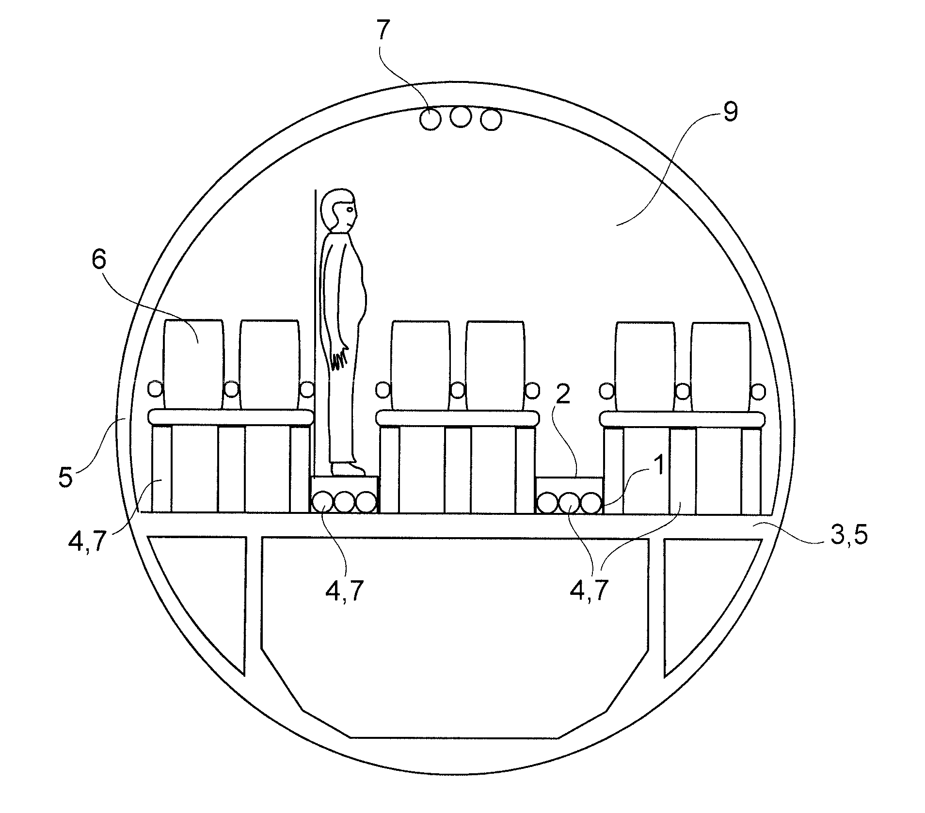
[0035]FIG. 3 shows an exemplary embodiment of the under-floor system for providing a functional space for an aircraft. The under-floor system comprises a support-member structure 1 and a cover element 2. The support-member structure 1 is designed such that the support-member structure 1 can be fastened to an aircraft structure element 3. The cover element 2 of a support-member structure 1 can be fastened such that the cover element 2 is spaced apart from the aircraft floor 3. By means of the spacing of the cover element 2 from an aircraft floor 3 the functional space 4 may be provided.

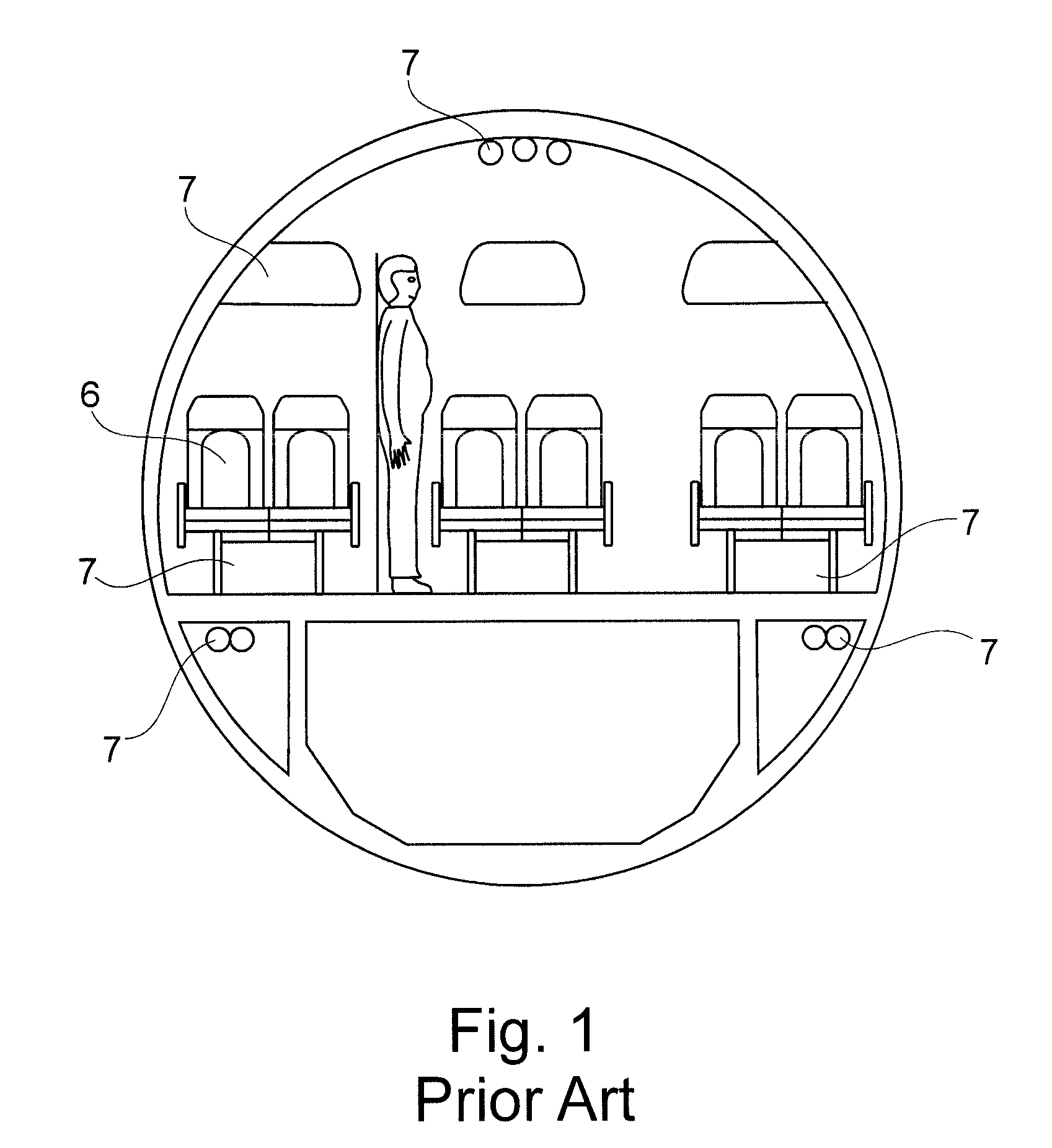
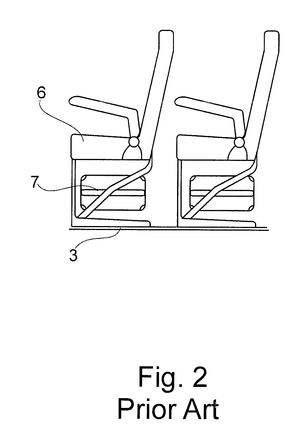
[0036]FIGS. 1 and 2 provide an overview of storage options in aircraft cabins without an additional functional space. The functional elements 7, for example items of baggage, pipelines, electrical lines or system...


PUM


Abstract

The present invention relates to an under-floor system for providing a functional space for an aircraft. The under-floor system comprises a support-member structure and a cover element. The support-member structure is designed such that the support-member structure can be fastened to an aircraft structure element. The cover element can be fastened to the support-member structure such that the cover element is spaced apart from, for example, the aircraft floor. By means of spacing the cover element apart from the aircraft floor, the functional space can be provided.

Description

REFERENCE TO RELATED APPLICATIONS[0001]This application claims the benefit of the filing date of German Patent Application No. 10 2007 015 520.6 filed Mar. 30, 2007 and of U.S. Provisional Patent Application No. 60 / 909,069 filed Mar. 30, 2007, the disclosures of which applications are hereby incorporated herein by reference.FIELD OF THE INVENTION[0002]The present invention relates to an under-floor system and a method for providing a functional space for an aircraft, as well as to the use of an under-floor system in an aircraft, and to an aircraft comprising an under-floor system.BACKGROUND OF THE INVENTION[0003]In aircraft cabins there is an ever increasing requirement for storage options for items of baggage and system elements, for example lines or pipes. Up to now, items of cabin baggage, i.e. baggage which passengers are allowed to take along into the aircraft cabin, had to be placed exclusively under the seat or in the overhead region, in the overhead stowage bins. In the over...

Claims


Application Information

Patent Timeline
Patent Type & Authority Applications(United States)
IPC IPC(8): B64C1/18B64D11/06
CPCB64C1/18B64D11/00Y02T50/46B64D2011/0662B64D2011/0617B64D11/0601B64D11/0636Y02T50/40
Inventor HERZOG, MARKDUPONT, MICHAEL
Owner AIRBUS OPERATIONS GMBH
Why Eureka
Try Eureka