Charger

a technology of charging rods and charging rods, applied in the field of charging rods, to achieve the effect of small space and simple structur

Inactive Publication Date: 2010-05-13
CHENG UEI PRECISION IND CO LTD
View PDF2 Cites 83 Cited by
  • Summary
  • Abstract
  • Description
  • Claims
  • Application Information

AI Technical Summary

Benefits of technology

[0006]As described above, the above-mentioned charger utilizes the locating body to cooperate with the locating ribs so as to make the plug well located, instead of a locating pole, a spring and a contact portion cooperating with contact surfaces of a cube according to a conventional technology. Therefore, the charger has a simple structure and the locating body occupies a relatively small space in the shell assembly.

Problems solved by technology

However, the combination of the locating pole, the spring and the contact portion together has a complicated structure and occupies a relatively large space in the shell assembly.

Method used


Image

  • Charger
  • Charger
  • Charger

Examples


Embodiment Construction

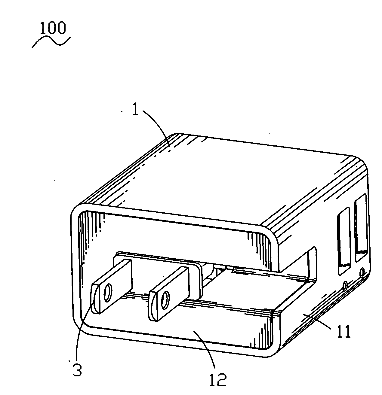
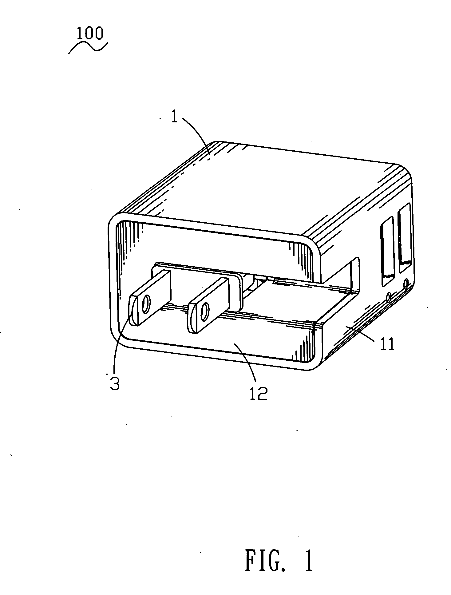
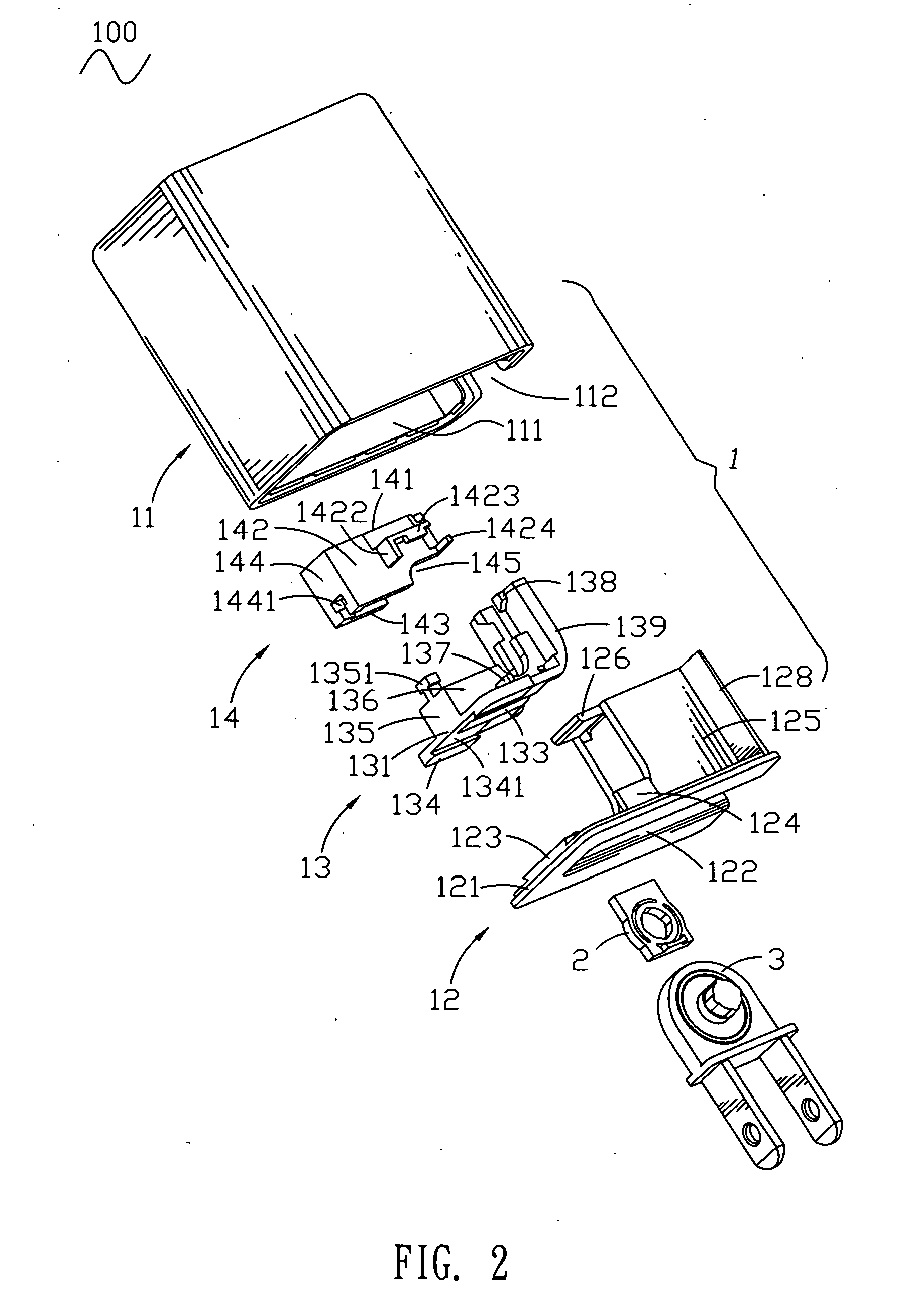
[0014]With reference to FIG. 1 and FIG. 2, a charger 100 according to the present invention includes a shell assembly 1, a locating body 2 and a plug 3 disposed in the shell assembly 1 respectively.

[0015]Referring to FIG. 2 and FIG. 4, the shell assembly 1 includes a first receiving shell 11, a second receiving shell 12, a first pivoting shell 13 and a second pivoting shell 14. The first receiving shell 11 is a rectangular cylindrical shape and defines a rectangular receiving recess 111 having a front communicating with the outside therein. A right side of the first receiving shell 11 defines a rectangular side window 112 communicating with the receiving recess 111 and having a front opened freely.

[0016]The second receiving shell 12 has a rectangular base plate 121 disposed vertically. The base plate 121 defines a rectangular first guiding window 122 passing therethrough and having a right end penetrating through a right side of the base plate 121 to be opened freely. The base plate...


PUM


Abstract

A charger includes a shell assembly defining a receiving space therein, a locating body fixed in the shell assembly and defining a locating cavity and a plurality of locating fillisters communicating with the locating cavity, and a plug pivotally received in the receiving space and having a base portion and at least two conductive blades fixed partially in the base portion. The base portion protrudes oppositely to form a pair of pivoting shafts pivoted in the shell assembly. A free end of one of the pivoting shafts defines a locating pillar pivoted in the locating cavity of the locating body. A side surface of the locating pillar protrudes outward to form a plurality of locating ribs buckled into the corresponding locating fillisters of the locating body when the conductive blades of the plug are completely rotated into and out of the receiving space.

Description

BACKGROUND OF THE INVENTION[0001]1. Field of the Invention[0002]The present invention generally relates to a charger, and more particularly to a charger with a rotatable plug.[0003]2. The Related Art[0004]A conventional charger includes a shell assembly and a plug having a pivoting shaft. The pivoting shaft of the plug is pivoted in the shell assembly in order to make the plug be able to be either rotated out from the shell assembly for being in use or rotated into the shell assembly for being put away. Two ends of the pivoting shaft respectively define a cube. Four side surfaces of each cube are defined as four corresponding contact surfaces. The shell assembly defines two locating poles respectively inserted in two springs. One end of each spring has a contact portion connected thereon. The contact portions abut against the corresponding contact surfaces of the cubes so as to ensure that the plug can be either firmly received in the shell assembly to be well put away or firmly str...

Claims


Application Information

Patent Timeline
Patent Type & Authority Applications(United States)
IPC IPC(8): H02J7/02H01R13/46H02J7/00
CPCH02J7/0042H05K5/02H02J2007/0062H01R35/04H02J7/00
Inventor WANG, KE-GUAN
Owner CHENG UEI PRECISION IND CO LTD
Why Eureka
Try Eureka