Image sensors having gratings for color separation

a color separation and image sensor technology, applied in the field of image sensors, can solve the problems of destructively destroying affecting the other pixels within the color kernel, so as to improve the color crosstalk and increase the qe

Active Publication Date: 2010-05-13
OMNIVISION TECH INC
View PDF25 Cites 77 Cited by
  • Summary
  • Abstract
  • Description
  • Claims
  • Application Information

AI Technical Summary

Benefits of technology

[0010]The present invention has the advantage of improving color crosstalk between adjacent pixels and increasing QE.

Problems solved by technology

This object is achieved by adjusting optical path differences for each pixel in a color kernel such that for a specific wavelength the light intensity falling onto the image sensor interferes constructively near the surface of one pixel and destructively for the other pixels within the color kernel.
For another specific wavelength, light interferes constructively near the surface of a second pixel and destructively for the other pixels within the color kernel.

Method used


Image

  • Image sensors having gratings for color separation
  • Image sensors having gratings for color separation
  • Image sensors having gratings for color separation

Examples


Embodiment Construction

[0031]An optical path as defined herein is:

optical path=n×d,   (Eq. 1)

where n is the index of refraction and d is the thickness of the material through which the light is passing.

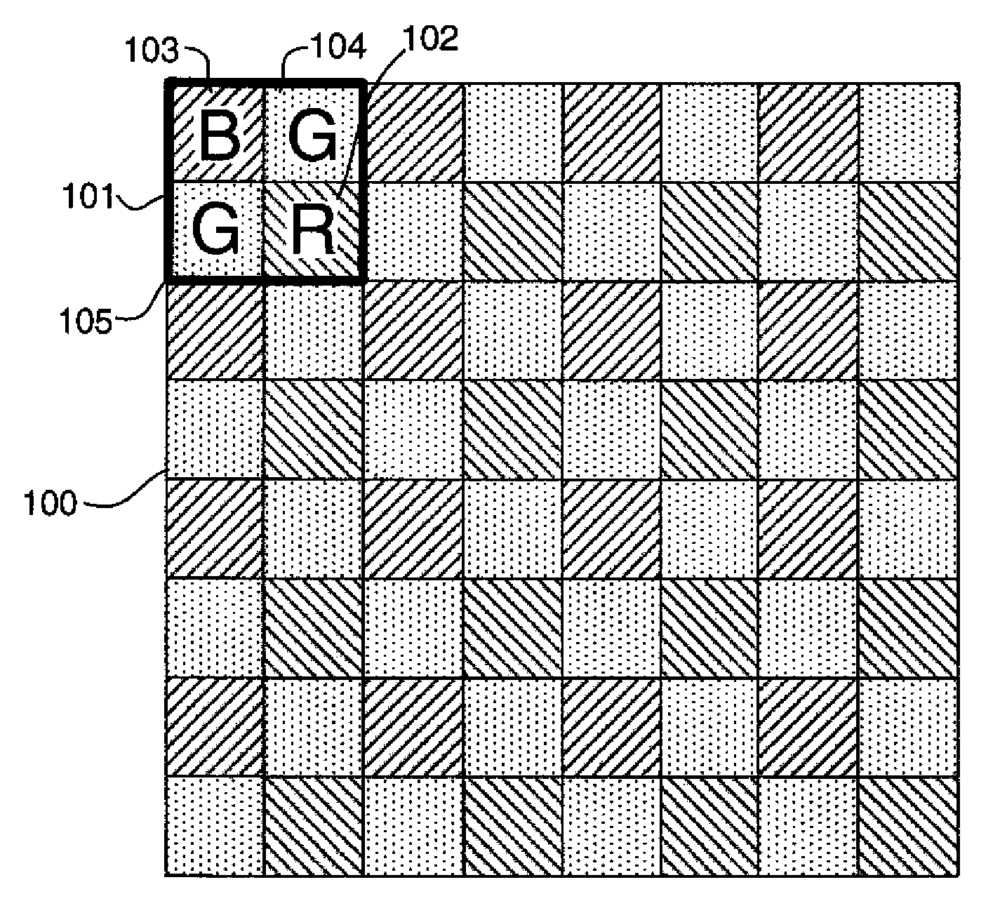
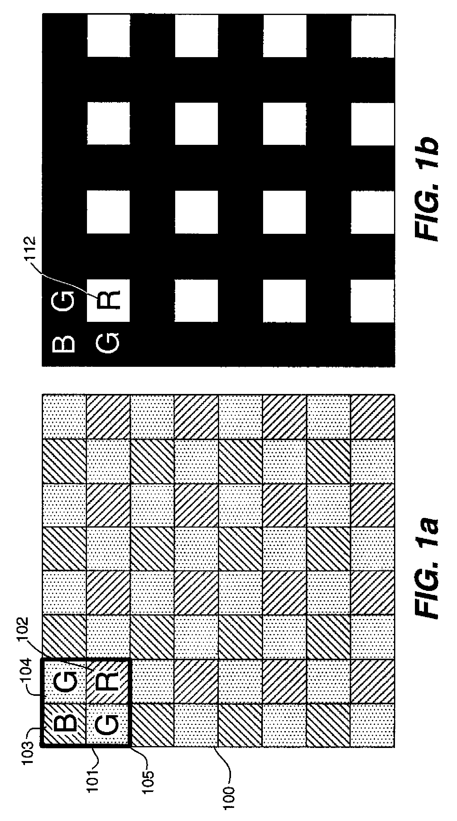
[0032]Turning now to FIG. 7, there is shown a portion of an image sensor array 401 of an image sensor of the first embodiment of the present invention. It is noted that, although the cross section only shows four pixels for simplicity, the image sensor array 401 typically includes thousands or millions of pixels. It is further noted that the image sensor array 401 is typically a part of an active pixel sensor as will be discussed in FIG. 19. Referring back to FIG. 7, the image sensor array 401 includes a plurality of pixels 301 and 302 disposed in an active layer 420. The pixels 301 and 302 are preferably grouped together in a 2×2 array, hereinafter a color kernel, that repeats over the array as will be described in detail hereinbelow. Although a 2×2 array is preferred, other color kernel sizes may also be ...


PUM


Abstract

An image sensor includes an array of pixels comprising a plurality of kernels that repeat periodically and each kernel includes n photosensitive regions for collecting charge in response to light, n is equal to or greater than 2; and a transparent layer spanning the photosensitive regions having n optical paths, at least two of which are different, wherein each optical path directs light of a predetermined spectral band into specific photosensitive regions.

Description

FIELD OF THE INVENTION[0001]The present invention generally relates to image sensors having an array of pixels subdivided into kernel of pixels, and more particularly to such image sensors having different optical paths for pixels in the kernel for improving color separation and increasing quantum efficiency.BACKGROUND OF THE INVENTION[0002]In general, as pixels made using CMOS processes for image sensors scale to smaller dimensions, several performance properties of the imagers using these pixels degrade. One performance property in particular, quantum efficiency (QE), degrades quickly. The loss in performance is confounded with the addition of a color-filter-array (CFA) on top of the pixel array. The purpose of the CFA is to allow for color separation of the incoming light for providing the ability to reconstruct color images. However, for a given wavelength, most of the filters are absorbing. Therefore, any given wavelength effectively sees a series of small apertures above the p...

Claims


Application Information

Patent Timeline
Patent Type & Authority Applications(United States)
IPC IPC(8): H04N5/335H01L21/00H01L27/088
CPCH01L27/14621H01L27/14685H01L27/1464H01L27/14627H01L27/14605H01L27/146H04N25/00
Inventor MCCARTEN, JOHN P.SUMMA, JOSEPH R.
Owner OMNIVISION TECH INC
Why Eureka
Try Eureka