Network timing synchronization systems

a network timing and synchronization technology, applied in multiplex communication, instruments, horology, etc., can solve the problems of high variation of delays, inaccurate synchronization, and significant number of clock cycles that can pass with the clock out of synchronization, so as to reduce the upgrade cost and upgrade time, and the effect of inexpensive and ubiquitous precision timing synchronization

Active Publication Date: 2010-05-13
RADULESCU CODRUT RADU
View PDF7 Cites 158 Cited by
  • Summary
  • Abstract
  • Description
  • Claims
  • Application Information

AI Technical Summary

Benefits of technology

[0021]Embodiments of the present invention provide for many advantages. Synchronization over PSN is attained under real levels of network propagation while meeting the stringent 50 ppb accuracy requirements of the telecommunications industry. Solutions, in accordance with the present invention, can easily be compiled into any network processor or FPGA chips that usually already exist in most telecom hardware, significantly decreasing upgrade costs and upgrade time for legacy systems.
[0022]Other embodiments can provide inexpensive and ubiquitous precision timing synchronization to virtually every system connected to a digital network. This is in contrast with current technology, where true precision timing is only achievable using expensive hardware-based systems, and which inhibits the advancement of low-cost technologies that might require precision timing.

Problems solved by technology

Furthermore, because the relay of synchronization in formation occurs relatively infrequently, a significant number of clock cycles can pass with the clock out of synchronization.
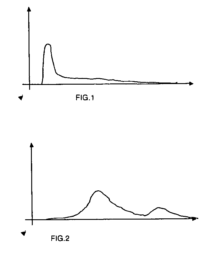
The wait, which is the major cause of propagation delay during transport, can be long and random so that the variation of the delays is high, and can be several magnitudes higher than the phase differences between the clocks.
Therefore, the assumption that such delays are constant and symmetrical will result in inaccurate synchronization.
The effectiveness of such statistical approaches can be limited, especially considering that the level of propagation delays can be a few magnitudes higher than that of the clock phase differences.
Consequently, a small estimation error will result in an error in synchronization.

Method used


Image

  • Network timing synchronization systems
  • Network timing synchronization systems
  • Network timing synchronization systems

Examples


embodiment example 1.2

Duet CFF Embodiment Example 1.2

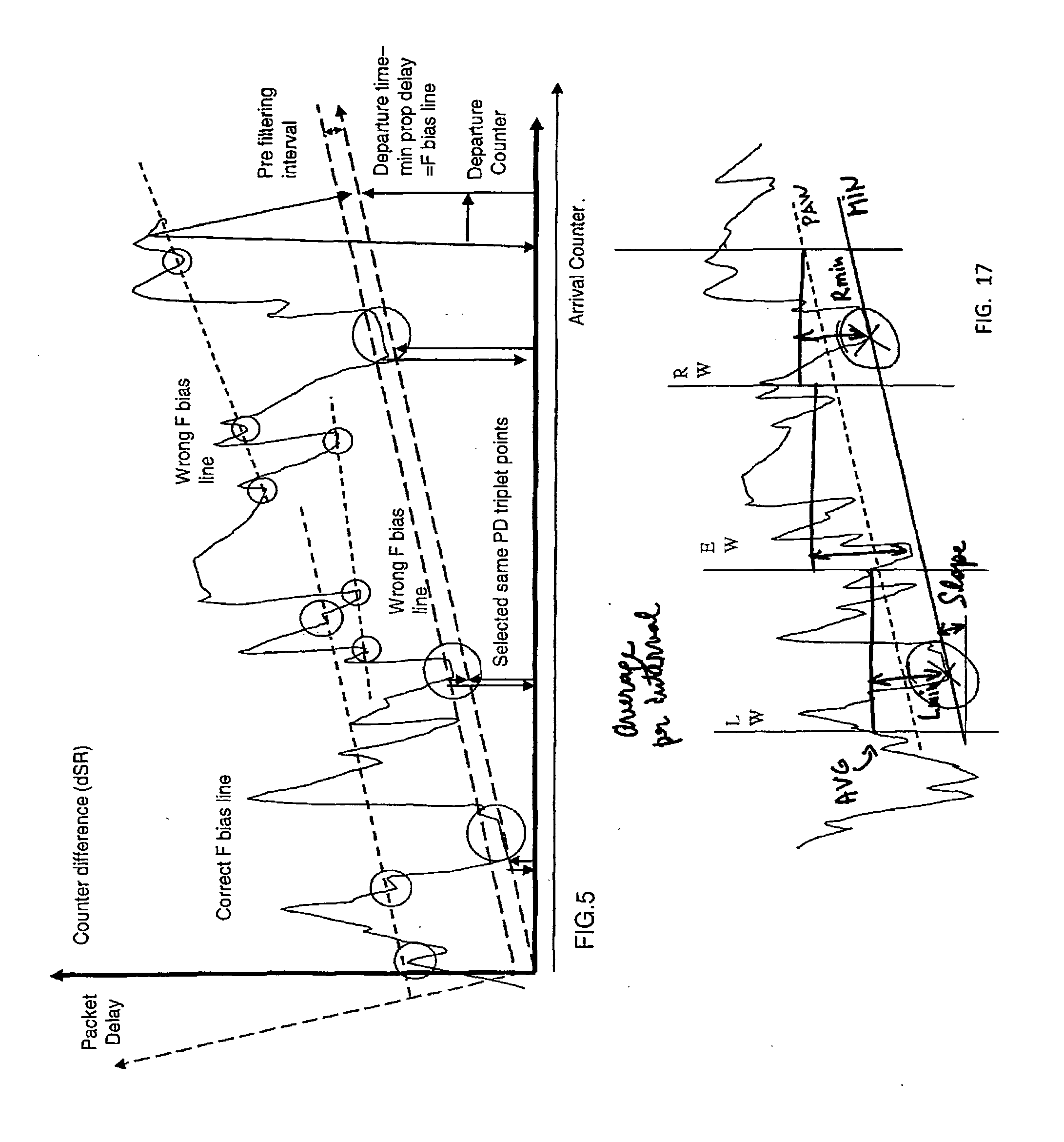
[0134]The difference between the local and the remote frequency results in a sloped distribution of TSP (Dn−An, An) events 222 on the graph in FIG. 23. Due to quantization error, stripes of densities may occur for the perfect propagation delay conditions. We can determine the position of the stripe that will encompass the maximum number of events inside WS, if local and remote QE is known (FIG. 24). Calculate CF for each of the TSP where D(n)−D(n−1)=dDn>min_distance. Distribution stripes may result from the quantization error at source or at destination (especially from the MII bus running at 25 MHz). Elements within one stripe (here named group) will not be mixed with the other group in the subsequent computings.

[0135]First Group is necessary to filter the VTs: −AT00.

[0136]Second Group is optional: QEmin−AT00+QEmax, if QEmax−QEmin

[0137]Third Group is also optional: −QEmax−AT00−QEmin, if QEmax−QEmin

[0138]Where QE is the quantizati...

example

[0379]Consider the topology: Master end, two intermediated switches: SW1, SW2 and Slave Reception (SR).

[0380]Master departure Time stamp=MT. Slave reception time stamp=SR

SR(n)=MT(n)+PDV1(n)+PDV2(n)+constant_PDV,

where n is the sequence ID and MT(n) is the master departure time stamp. The first switch SW1 will replace MT(n) by MT(n)+PDV1(n). The second switch SW2 will replace the received embedded time stamp (MT(n)+PDV1(n)) by MT(n)+PDV1(n)+PDV2(n).

[0381]The slave would determine the propagation delay=SR(n)−[MT(n)+PDV1(n)+PDV2(n)]=[0382]=MT(n)+PDV1(n)+PDV2(n)+constant_PDV−[MT(n)+PDV1(n)+PDV2(n)]=[0383]=constant_PDV.

[0384]In real life there are also variable delays at physical link layer (here marked as constant_PDV) but overall this protocol will improve significantly—by orders of magnitude—the accuracy of timing calculations.

[0385]IV. Method and Apparatus for Simulation, Test and Debug

[0386]Software Simulation Test Bench

[0387]Our Algorithm receives time stamps from the protocol stack...


PUM


Abstract

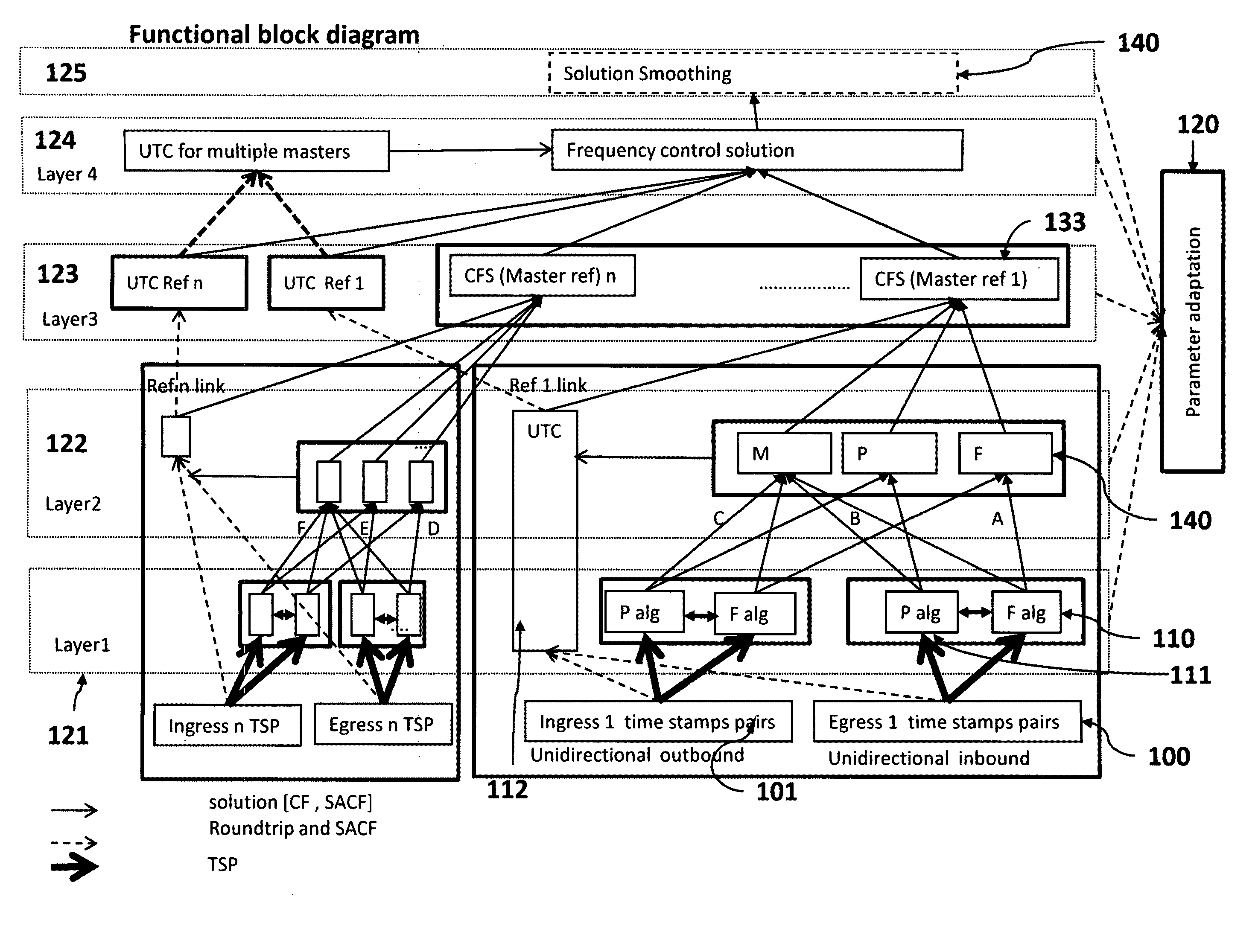
A method and means synchronize timing of a follower system to a reference system. A Hierarchical CFF function (“HCFF”) is applied to a set of Correction Factor Functions types (“CFFs”) or a set of other HCFF. Each CFF type uses the same input data set specific to that type and generates at least one Correction Factor Solution (“CFS”) for each of the CFF, wherein the CFS consists of only CF or the CFS consists of both i) CF and ii) a SACF. The HCFF takes as input a set of CFS and generates at least one CFS, wherein the CFS consist of only the CF, or the CFS consists of both the i) CF and ii) a SACF.

Description

[0001]This application claims the benefit of provisional application No. 61 / 192,8046, filed Sep. 22, 2008, the disclosure of which is incorporated in its entirety by reference thereto.BACKGROUND OF THE INVENTION[0002]1. Field of the Invention[0003]The present invention relates to timing synchronization across a network with one or more timing reference nodes; more particularly to a system that provides precision timing reference through a variety of links to a plurality of follower network nodes.[0004]2. Description of the Prior Art[0005]Synchronization of clocks between computers can be effected anywhere on, above or within, the planet, or in fact anywhere within the Universe. Timing synchronization includes clock synchronization for Frequency, Phase and Time of Day.[0006]Many extant protocols / methodologies, and implementations thereof, exist regarding the field of clock synchronization. For example, Network Time Protocol (NTP), GPS Protocol and Precision Time Protocol (IEEE (1588)...

Claims


Application Information

Patent Timeline
Patent Type & Authority Applications(United States)
IPC IPC(8): H04J3/06
CPCH04J3/0667G04G7/00
Inventor RADULESCU, CODRUT RADU
Owner RADULESCU CODRUT RADU
Why Eureka
Try Eureka