Demodulating apparatus and demodulating method
a demodulating apparatus and demodulating method technology, applied in the field of demodulating apparatus and demodulating method, can solve the problems of troublesome procedure for users, difficulty in detecting the presence or absence of channel inversion, etc., and achieve the effect of facilitating the demodulation of input signals
- Summary
- Abstract
- Description
- Claims
- Application Information
AI Technical Summary
Benefits of technology
Problems solved by technology
Method used
Image
Examples
first embodiment
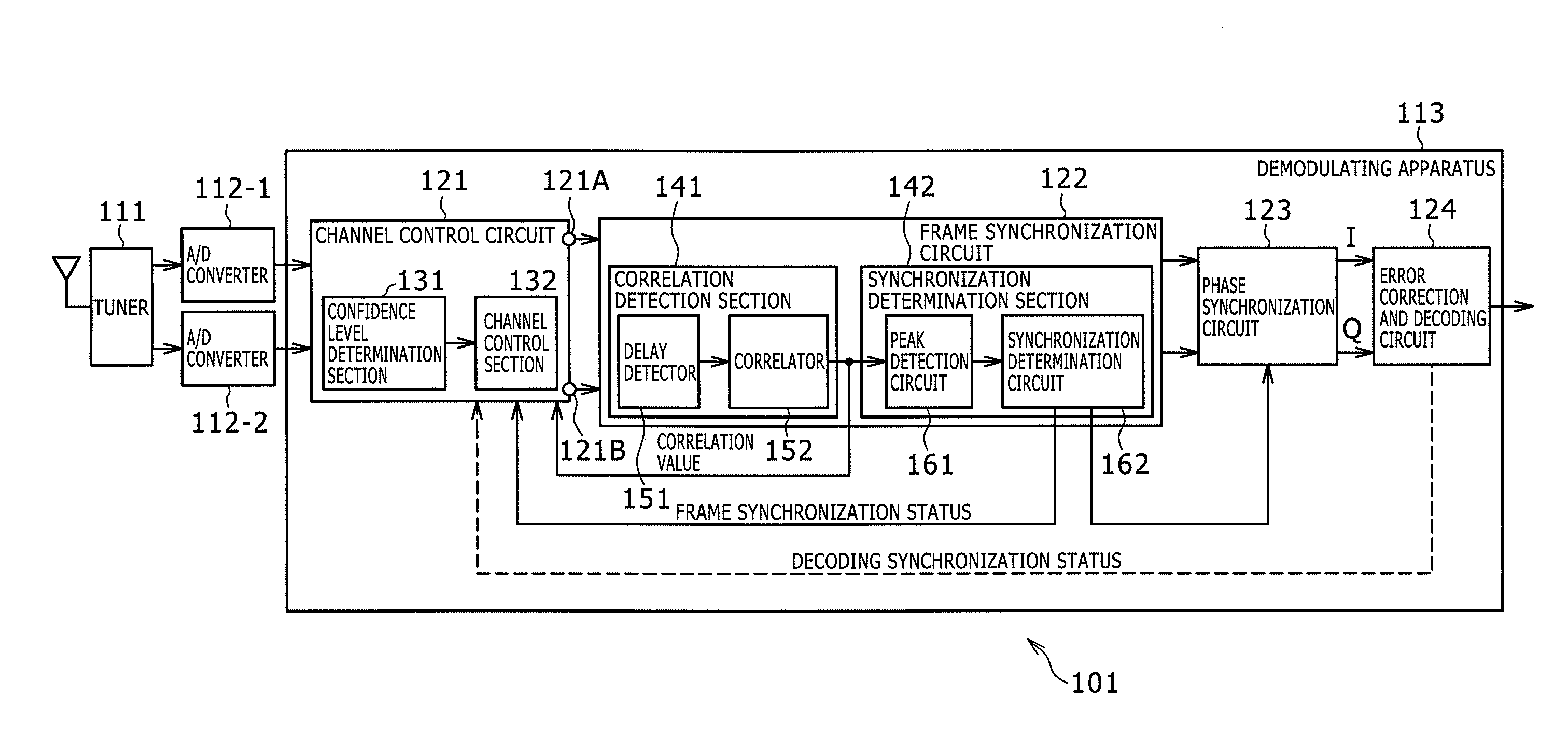
[0105]Explained below in reference to the flowchart of FIG. 19 is how the channel control process is executed by the channel control circuit 121 in relation to the frame synchronization process of FIG. 10.
[0106]In step 521, the channel control section 132 determines whether or not the imaginary part of the correlation value is equal to or higher than zero. As discussed above in reference to FIG. 14, in an ideal reception environment where the channels of the input signal are not inverted, the correlation value at peak timing is given as Kej(π / 2+Δθ). On the other hand, as described above in reference to FIG. 18, in an ideal reception environment where the channels of the input signal are inverted, the correlation value at peak timing is given as Kej(−π / 2−Δθ). Accordingly, where the channels of the input signal are not inverted and where the angle Δθfalls within the range of ±π / 2, the imaginary part of the relative value takes a positive value at peak timing, and the correlation betwe...
second embodiment
[0113]Explained below in reference to the flowchart of FIG. 21 is how the channel control process is executed by the channel control circuit 121 in relation to the frame synchronization process of FIG. 10.
[0114]In step S41, the channel control section 132 determines whether frame synchronization has been established on the basis of the signal coming from the synchronization determination circuit 162. If frame synchronization is not found to have been established, control is passed on to step S42.
[0115]In step S42, the channel control section 132 determines whether a predetermined time period has elapsed. If the predetermined time period is not found to have elapsed, i.e., if the state of frame asynchronism is not found to have lasted for the predetermined time period, control is returned to step S41. Steps S41 and S42 are repeatedly executed until frame synchronization is found to have been established in step S41, or until the predetermined time period is found to have elapsed in s...
third embodiment
[0120]Explained below in reference to the flowchart of FIG. 22 is how the channel control process is executed by the channel control circuit 121 in relation to the frame synchronization process of FIG. 10.
[0121]In step S61, the confidence level determination section 131 determines whether the power of the correlation value is higher than a predetermined threshold value. The power of the correlation value becomes higher, the larger the absolute value of the correlation value becomes. Ideally, the correlation value at peak timing is K2. Conversely, the higher the power of the correlation value, the larger the absolute value of the correlation value. That is, there appears a strong correlative relationship between the received delayed detection sequence and the known delayed detection sequence, which indicates a high confidence level of the correlation value. If the power of the correlation value is found to be higher than the predetermined threshold value, the confidence level determi...
PUM
 Abstract
Description
Claims
Application Information
 - R&D
- Intellectual Property
- Life Sciences
- Materials
- Tech Scout
- Unparalleled Data Quality
- Higher Quality Content
- 60% Fewer Hallucinations
Browse by: Latest US Patents, China's latest patents, Technical Efficacy Thesaurus, Application Domain, Technology Topic, Popular Technical Reports.
© 2025 PatSnap. All rights reserved.Legal|Privacy policy|Modern Slavery Act Transparency Statement|Sitemap|About US| Contact US: help@patsnap.com


