Manufacturing method of glass molded body, manufacturing apparatus of glass molded body, and glass molded body

a manufacturing apparatus and glass technology, applied in glass making apparatus, manufacturing tools, instruments, etc., can solve the problem of long time for one-time shape creation, and achieve the effect of high accuracy, stable quality and efficient manufacturing

Inactive Publication Date: 2010-05-13
KONICA MINOLTA OPTO
View PDF3 Cites 41 Cited by
  • Summary
  • Abstract
  • Description
  • Claims
  • Application Information

AI Technical Summary

Benefits of technology

[0029]According to the present invention, when a predetermined time has elapsed after detecting that a dropped molten glass droplet has reached a predetermined position, pressing for the molten glass droplet by a shaping mold is stated. Therefore, a period of time after the molten glass droplet has come in contact with the lower mold until press molding is started is maintained constant with high accuracy. Therefore, at the time of manufacturing many glass shaped-bodies repeatedly, even if dispersion arises in dropping intervals, dispersion in the temperature of the molten glass droplet at the time of press molding can be suppressed to the minimum, whereby a glass molded body can be manufactured efficiently with stable quality.

Problems solved by technology

However, this method needs to repeat heating and cooling a glass molded body and a shaping mold for each shaping shot, and in order to suppress dispersion in temperature at the time of conducting press shaping and to conduct the shaping with sufficient reproducibility, it has a fundamental problem that the shaping for one time takes a very long time.

Method used


Image

  • Manufacturing method of glass molded body, manufacturing apparatus of glass molded body, and glass molded body
  • Manufacturing method of glass molded body, manufacturing apparatus of glass molded body, and glass molded body
  • Manufacturing method of glass molded body, manufacturing apparatus of glass molded body, and glass molded body

Examples


embodiment 1

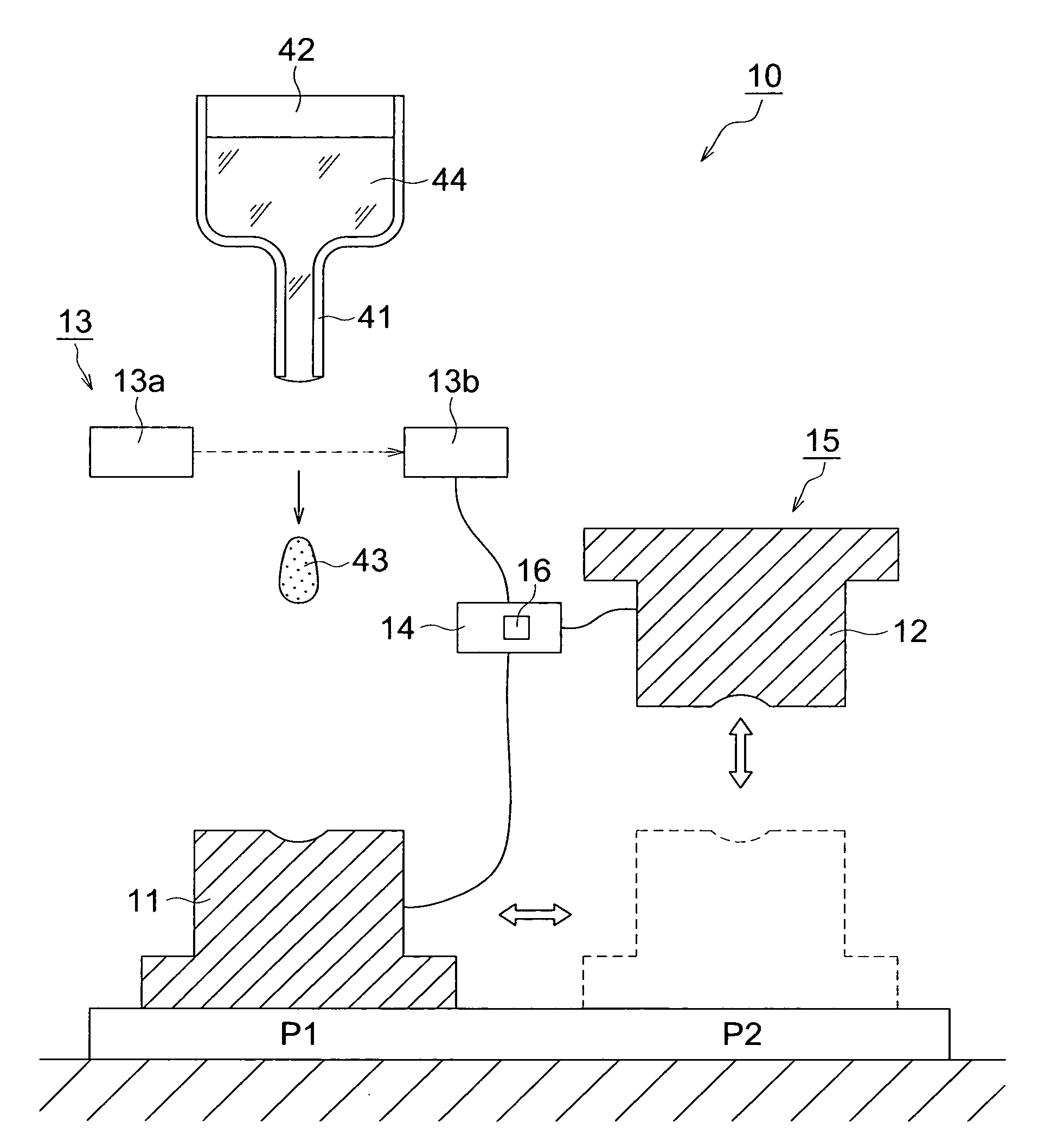
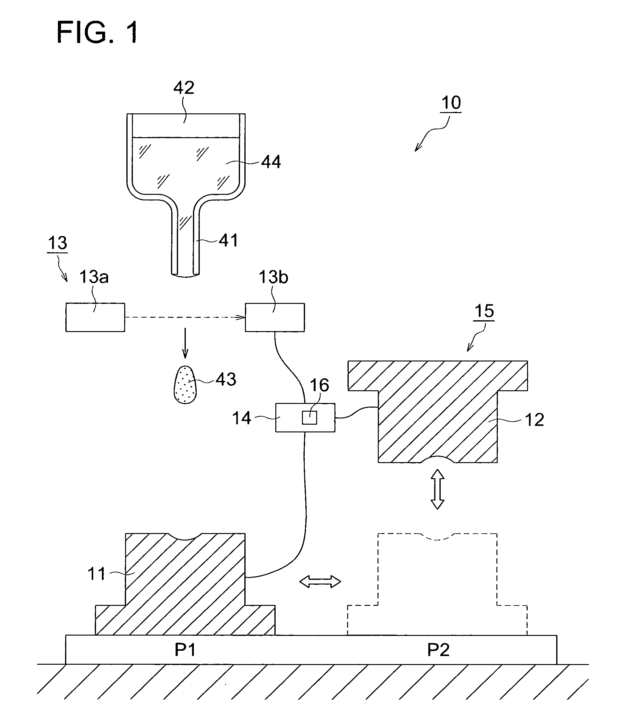
[0055]The manufacturing method of a glass molded body according to the first embodiment of the present invention will be explained with reference to FIGS. 1 to 3. FIGS. 1 and 2 are schematic diagrams showing a manufacturing apparatus 10 of a glass molded body, which is used in this embodiment. FIG. 1 shows the state of a supplying process of dropping a molten glass droplet from a nozzle and supplying it to a lower mold, and FIG. 2 shows the state of a pressing process of pressing the supplied molten glass droplet with a shaping mold, respectively. Further, FIG. 3 is a flowchart showing the manufacturing method of a glass molded body in this embodiment.

[0056]The manufacturing apparatus 10 of the glass molded body shown in FIGS. 1 and 2 has a shaping mold 15 which includes a lower mold 11 and a upper mold 12 and is used to conduct press molding for a molten glass droplet 43. Further, as a supplying section to supply a molten glass droplet 43 to the lower mold 11, the manufacturing app...

embodiment 2

[0080]Next, the manufacturing method of a glass molded body as the second embodiment of the present invention will be explained with reference to FIG. 4. FIG. 4 is a schematic diagram showing a manufacturing apparatus 20 of a glass molded body, which is used in the second embodiment, and shows the state of a supplying process of dropping a molten glass droplet 43 from a nozzle 41 and supplying it to a lower mold 11.

[0081]The difference of the manufacturing apparatus 20 of a glass molded body from the manufacturing apparatus 10 of a glass molded body in the first embodiment explained previously is in a detecting section for detecting that a dropped molten glass droplet 43 has arrived at a predetermined position. The manufacturing apparatus 20 of a glass molded body shown in FIG. 4 has a weight sensor 21 in the lower part of the lower mold 11. If the weight sensor 21 detects an impulse force generated when a molten glass droplet 43 dropped from the nozzle 41 collides with the lower mo...

embodiment 3

[0084]Next, the manufacturing method of a glass molded body as the third embodiment of the present invention will be explained with reference to FIG. 5 and FIG. 6. FIG. 5 is a schematic diagram showing a manufacturing apparatus 30 of a glass molded body, which is used in the third embodiment, and shows the state of a supplying process of dropping a molten glass and supplying it to a lower mold. FIG. 6 is a flowchart showing the manufacturing method of a glass molded body in this embodiment.

[0085]The difference of the manufacturing apparatus 30 of a glass molded body from the manufacturing apparatus 10 of a glass molded body in the first embodiment explained previously is in that the manufacturing apparatus 30 has a member 36 provided with a small through hole 34 in order to supply a minute molten glass droplet 33 to a lower mold. Further, a shaping mold 35 includes a lower mold 31 and an upper mold 32 with respective small molding surfaces. Other structures are the same as those of ...


PUM

PropertyMeasurementUnit
weightaaaaaaaaaa
timeaaaaaaaaaa
timeaaaaaaaaaa

Abstract

A process for producing a glass molding, in which a glass molding of stable quality can be efficiently produced through minimizing of temperature fluctuation of molten glass drops at pressure molding operation; and an apparatus for production of a glass molding used in this process. Molten glass drops are fed into an inferior die by causing the molten glass drops to fall from above toward the inferior die. The arrival of molten glass drops having fallen at a given location is detected, and pressurization of the molten glass drops by means of molding dies is initiated upon the passage of a given time since the detection.

Description

TECHNICAL FIELD[0001]The present invention relates to a manufacturing method of a glass molded body which can be used as various kinds of optical elements, a manufacturing apparatus of a glass molded body and a glass molded body.BACKGROUND ART[0002]In recent years, as lenses for digital cameras, optical pickup lenses for DVD, etc., lenses for cameras of mobile phones, coupling lenses for optical communications, and the like, optical elements made of glass are used widely. As such optical elements made of glass, glass molded bodies manufactured by a process of conducting press molding for glass materials with a shaping mold have been used more often.[0003]In the conventional method (hereafter, referred to as “reheat-pressing method”) which has been used widely as a manufacturing method of a glass molded body, a glass material used for manufacturing a molded body is produced preliminary to have a specified weight and shape, and is heated together with a shaping mold to a temperature a...

Claims


Application Information

Patent Timeline
Patent Type & Authority Applications(United States)
IPC IPC(8): C03C3/00C03B11/08G12B1/00
CPCC03B11/16
Inventor HAYAMIZU, SHUNICHIKAMADA, YOSHIHIROSUGIYAMA, TADASHISERADA, KAORU
Owner KONICA MINOLTA OPTO
Why Eureka
Try Eureka